Method and apparatus for evaluating and debugging assertions

a technology of assertion and assertion, applied in the field of electronic design automation, can solve the problems of generating automatic error messages, requiring huge amounts of time and computing power to generate and execute, and being more exhaustive, and achieve the effect of improving efficiency

Active Publication Date: 2006-04-20
SYNOPSYS INC
View PDF3 Cites 41 Cited by
  • Summary
  • Abstract
  • Description
  • Claims
  • Application Information

AI Technical Summary

Benefits of technology

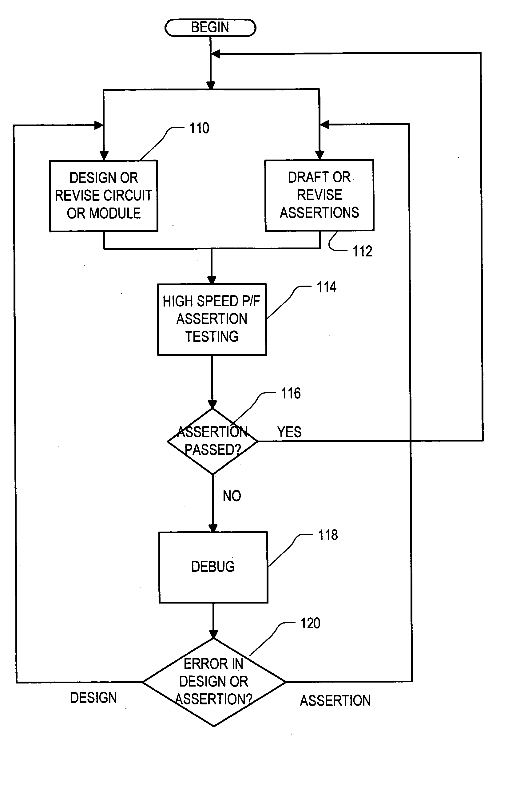
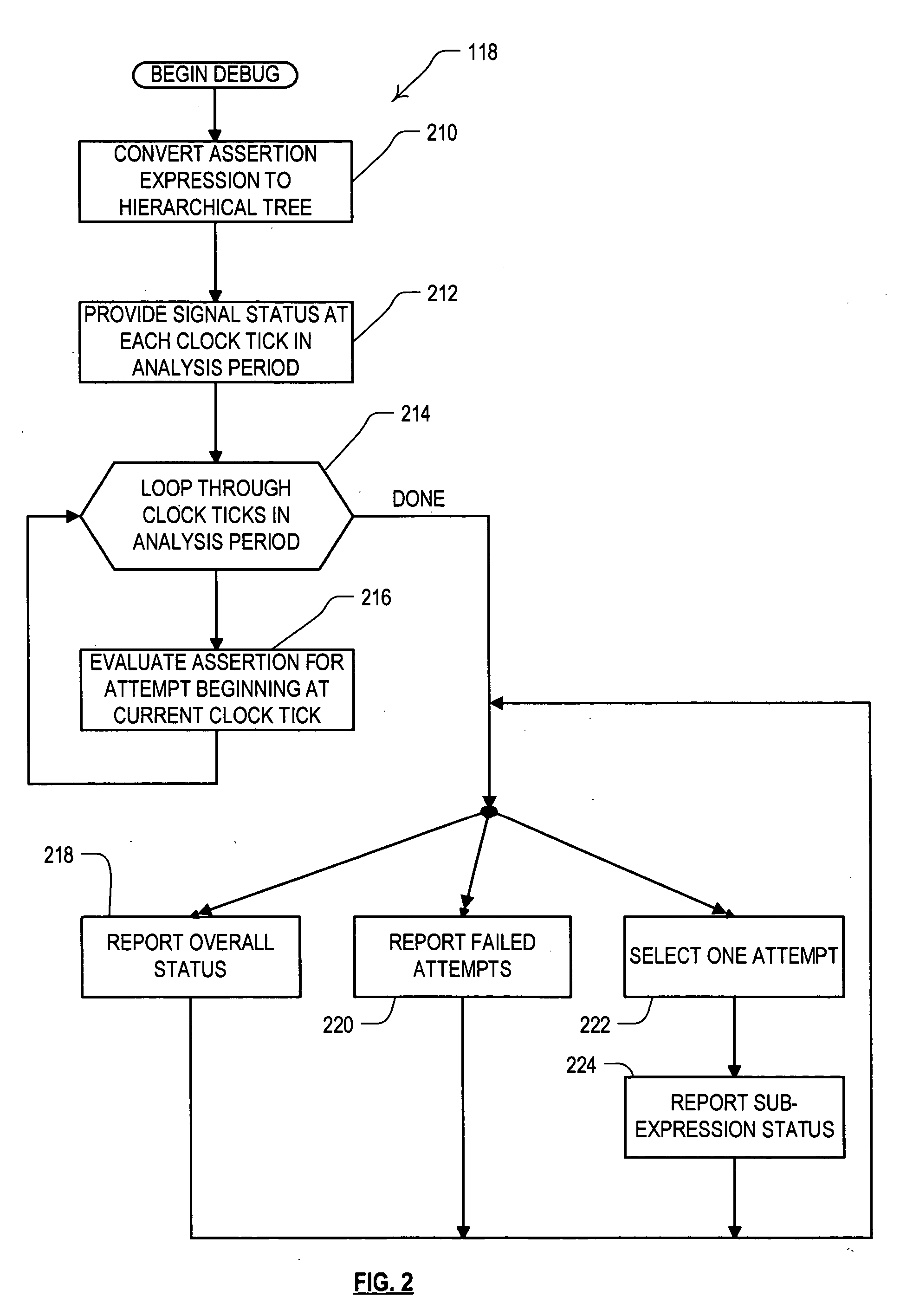
[0014] In an embodiment, a recursive descent algorithm is used to evaluate the assertion expression. The assertion expression is first parsed into a tree structure, which is then evaluated for some set of attempt times over a finite time interval. The algorithm advantageously caches assertion “sub-attempt” results at each node in the tree so as to improve efficiency. The algorithm produces complete activity trace information over the entire time window, and does not require a state machine to be generated

Problems solved by technology

The latter methods are more exhaustive than the former, but can require huge amounts of time and computing power to generate and execute.
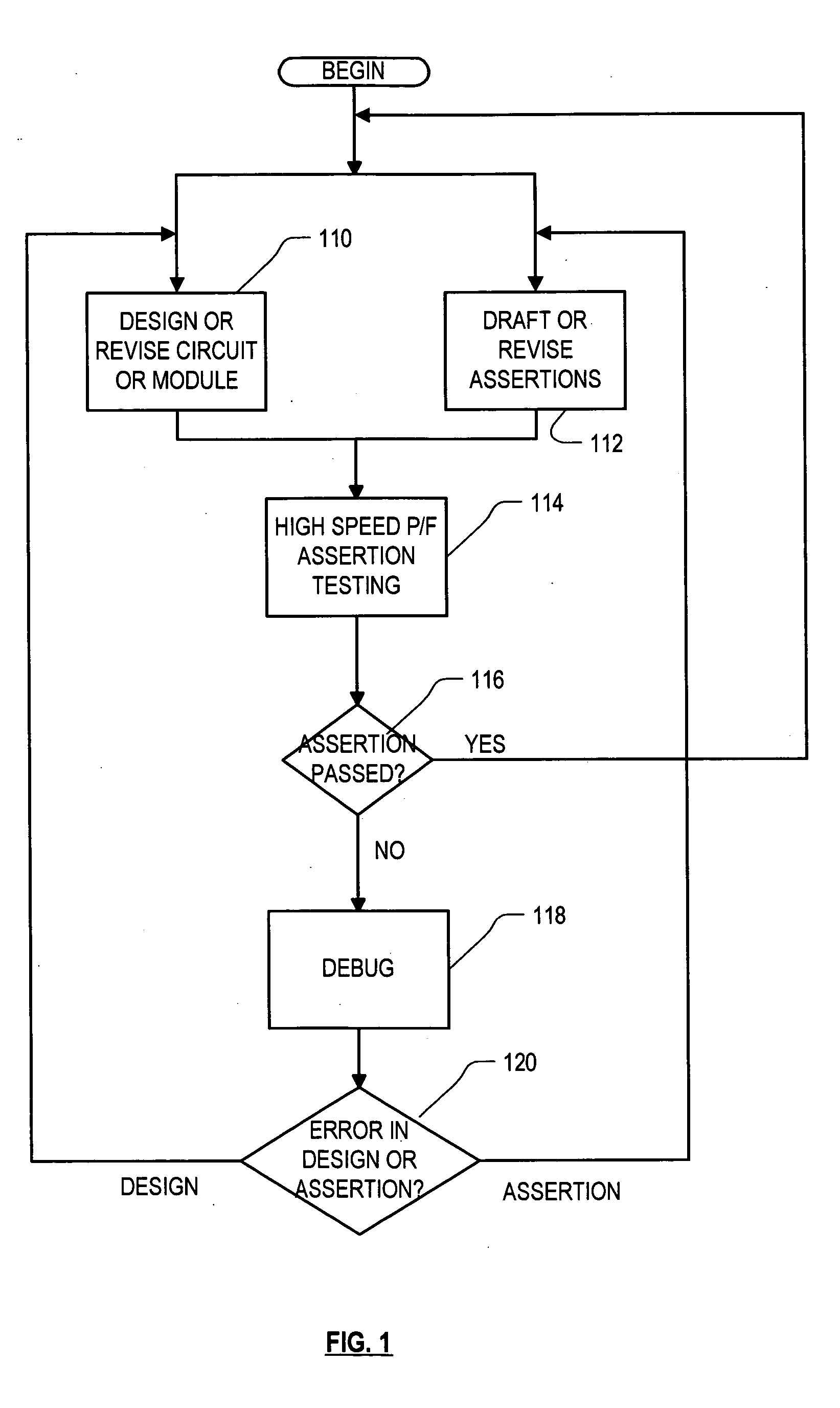
Assertions allow for automated checking that the specified property is true, and can generate automatic error messages if the property is not true.
Unfortunately, the resulting state machines usually bear little or no resemblance to the original assertion expression to the average user.
Verification tools therefore usually report whether an assertion passed or failed, and if it failed then for which attempt it failed, but usually cannot provide any further information about the failure.
Even where the tools provide information about the state of the state machine upon failure, the average user has no way to relate such information to either the assertion expression or the circuit design.
Designers therefore know that the circuit design failed to perform in accordance w

Method used


Image

  • Method and apparatus for evaluating and debugging assertions
  • Method and apparatus for evaluating and debugging assertions
  • Method and apparatus for evaluating and debugging assertions

Examples


example implementation

[0124] Set forth in the Appendix hereto is Python-like pseudocode describing an example set of algorithms implementing the above-described functions. Note that the # symbol in this pseudocode indicates that a comment follows until the end of the line. In the example, it is assumed that the assertion statements are coded according to the System Verilog syntax, but other implementations can be developed for statements coded according to the specifications of other assertion-based languages.

[0125] The algorithm assumes that the sequential assertion expression to be evaluated is rendered unambiguously into a tree structure of nodes, such as that shown in FIG. 4. The only non-temporal subexpressions in the assertion expression are Boolean operands. Thus the tree nodes are either temporal operator nodes, denoted by s0,s1, . . . , or boolean operand nodes, denoted by b0,b1, . . .

[0126] The temporal operators defined are-the cycle delay (##[n:m]), repetition (*[n:m]), or, and, intersect, ...


PUM


Abstract

Roughly described, assertion expressions are evaluated against the binary signal values of a circuit simulation in such a way as to be able to report status information at intermediate levels of assertion subexpressions. In one embodiment, the status information reported for an intermediate subexpressions contains the final status of that subexpression in response to a given assertion attempt, at least to the extent it has been determined by the end of the evaluation period (e.g. pass, fail or indeterminate). In another embodiment, the status information reported for an intermediate subexpression contains a tick-by-tick analysis of the activity within that subexpression. In another embodiment, the status information for a subexpression can also contain a tick-by-tick analysis of the activity of an operator of the subexpression. Other kinds and levels of detail at the subexpression level can be provided in various other embodiments.

Description

COPYRIGHT DISCLAIMER [0001] A portion of the disclosure of this patent document contains material which is subject to copyright protection. The copyright owner has no objection to the facsimile reproduction by anyone of the patent document or the patent disclosure as it appears in the U.S. Patent and Trademark Office patent file or records, but otherwise reserves all copyright rights whatsoever. BACKGROUND [0002] 1. Field of the Invention [0003] The invention relates to electronic design automation, and more particularly to techniques for assertion-based verification of electronic designs. [0004] 2. Description of Related Art [0005] An electronic design automation (EDA) system is a form of computer aided design (CAD) system used for designing integrated circuit (IC) devices. The EDA system typically receives one or more high level behavioral descriptions of an IC device (e.g., in hardware description languages like VHDL, Verilog, etc.) and translates this high level design language ...

Claims


Application Information

Patent Timeline
IPC IPC(8): G06F17/50
CPCG06F17/5022G06F30/33
Inventor MOORBY, PHILIP R.
Owner SYNOPSYS INC
Why Eureka
Try Eureka