Implants and methods for treating bone

a technology of implants and bone, applied in the field of medical implants, can solve the problems of fractures in the spine and hips, affecting mobility and quality of life, and the advances in medical advances aimed at slowing or arresting bone loss from aging have not provided solutions to this problem

Active Publication Date: 2006-04-27
DFINE INC
View PDF80 Cites 168 Cited by
  • Summary
  • Abstract
  • Description
  • Claims
  • Application Information

AI Technical Summary

Benefits of technology

[0019] The invention provides a method of correcting numerous bone abnormalities including vertebral compression fractures, bone tumors and cysts, avascular necrosis of the femoral head and the like. The abnormality may be corrected by first accessing and boring into the damaged tissue or bone (FIG. 1). Th

Problems solved by technology

Medical advances aimed at slowing or arresting bone loss from aging have not provided solutions to this problem.
Osteoporosis affects the entire skeleton but most commonly causes fractures in the spine and hip.
Spinal or vertebral fractures also have serious consequences, with patients suffering from loss of height, deformity and persistent pain which can significantly impair mobility and quality of life.
Osteoporosis describes a condition of decreased bone mass that leads to fragile bones which are at an increased risk for fractures.
In an osteoporosic bone, the sponge-like cancellous bone has pores or voids that increase in dimension, making the bone very fragile.
In an elderly patient, bone resorption can surpass bone formation thus resulting in deterioration of bone density.
The bilateral transpedicular approach is typically used because inadequate PMMA infill is achieved with a unilateral approach.
Since the PMMA needs to be forced into cancellous bone, the technique requires high pressures and fairly low viscosity cement.
Since the cortical bone of the targeted vertebra may have a recent fracture, there is the potential of PMMA leakage.
Leakage of PMMA during vertebroplasty can result in very serious complications including compression of adjacent structures that necessitate emergency decompressive surgery.
The exothermic reaction of PMMA carries potential catastrophic consequences if thermal damage were to extend to the dural sac, cord, and nerve roots.
Vertebroplasty patients often return with new pain caused by a new vertebral body fracture.
Leakage of ceme

Method used


Image

  • Implants and methods for treating bone
  • Implants and methods for treating bone
  • Implants and methods for treating bone

Examples


Embodiment Construction

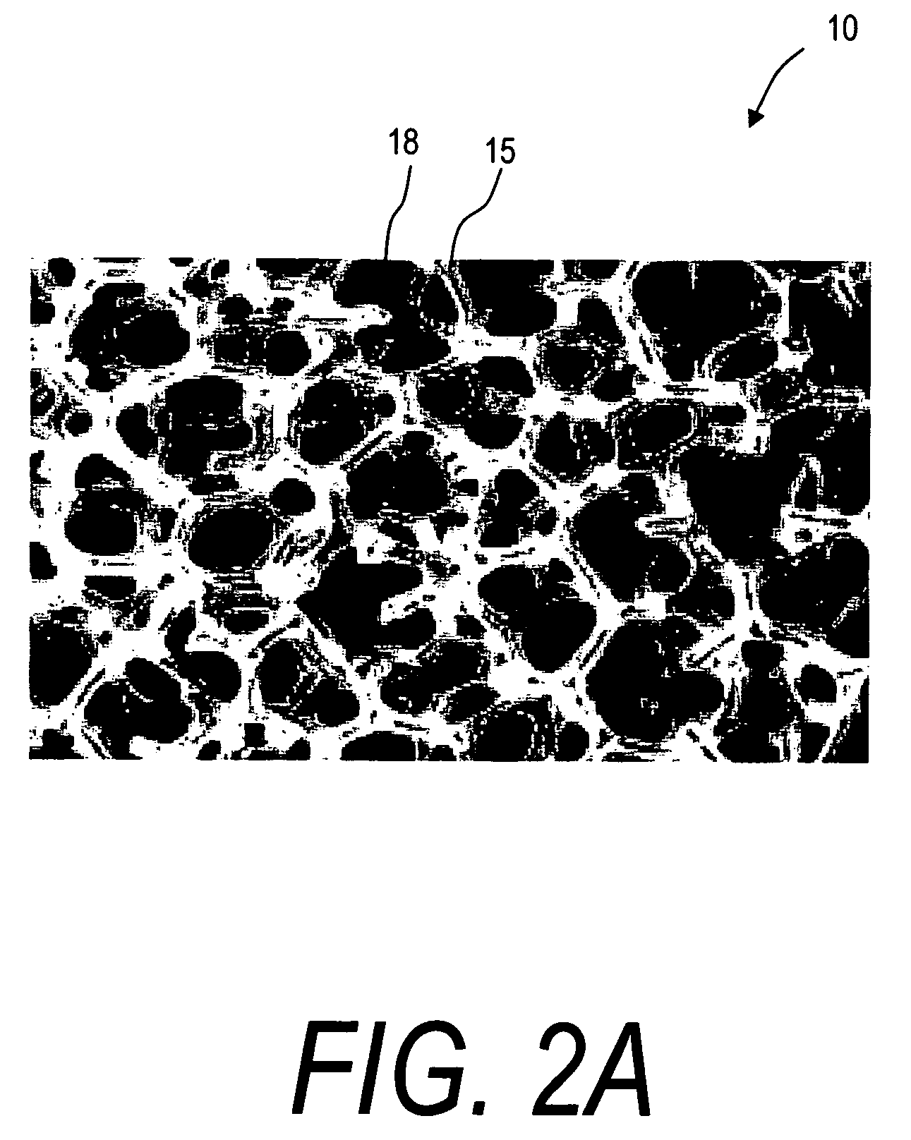
[0030] The present invention comprises a bone implant of a reticulated material that can be radially expanded in cross-section to support a bone, and more particularly to move apart cortical endplates to at leat partly restore vertebral height. In one embodiment, the implants elements comprise reticulated scaffold structures that can allow for later bone ingrowth. FIG. 2A illustrates a greatly enlarged view of an exemplary open cell reticulated material 10 corresponding to the invention that is useful for defining terms used herein to describe the implants. In general, the term reticulated means having the appearance of, or functioning as wire network or substantially rigid net structure. The related term reticulate mean resembling or forming a network. The terms reticulated, reticulate and trabecular are used interchangeably herein to describe structures having ligaments 15 that bound an open cells 18 or closed cell in the interior structure.

[0031] Such reticulated structures 10 a...


PUM

PropertyMeasurementUnit
Heightaaaaaaaaaa
Biodegradabilityaaaaaaaaaa
Fractureaaaaaaaaaa

Abstract

An orthopedic implant comprising a deformable, expandable implant body configured for treating abnormalities in bones, such as compression fractures of vertebra, necrosis of femurs and the like. An exemplary implant body comprises a small cross-section threaded element that is introduced into a bone region and thereafter is expanded into a larger cross-section, monolithic assembly to provide a bone support. In one embodiment, the implant body is at least partly fabricated of a magnesium alloy that is biodegradable to allow for later tissue ingrowth.

Description

CROSS-REFERENCE TO RELATED APPLICATIONS [0001] This application claims benefit of Provisional U.S. Patent Application Ser. No. 60 / 577,559 filed Jun. 7, 2004 (Docket No. S-7700-040) titled Reticulated Implants and Methods for Treating Abnormalities in Bone, the entire contents of which are hereby incorporated by reference in their entirety and should be considered a part of this specification.BACKGROUND OF THE INVENTION [0002] 1. Field of the Invention [0003] This invention relates to medical implants and more particularly to expandable open cell reticulated implants configured as bone support implants for treating abnormalities in bones such as compression fractures of vertebra, necrosis of femurs and the like. An exemplary implant body comprises a small cross-section threaded element that is introduced into a bone region and thereafter is expanded into a larger cross-section, open cell reticulated monolith to provide a bone support. [0004] 2. Description of the Related Art [0005] O...

Claims


Application Information

Patent Timeline
IPC IPC(8): A61F2/44
CPCA61B17/70A61B17/8858A61B2017/00004A61F2/44A61F2/4455A61F2/4611A61F2002/30062A61F2002/30289A61F2002/30579A61F2002/30677A61F2210/0004A61F2230/0091
Inventor TRUCKAI, CSABASHADDUCK, JOHN H.
Owner DFINE INC
Why Eureka
Try Eureka