Nitride semiconductor device
a technology of nitride and semiconductors, applied in the direction of semiconductor lasers, lasers, printing, etc., can solve problems such as property changes
- Summary
- Abstract
- Description
- Claims
- Application Information
AI Technical Summary
Benefits of technology
Problems solved by technology
Method used
Image
Examples
first embodiment
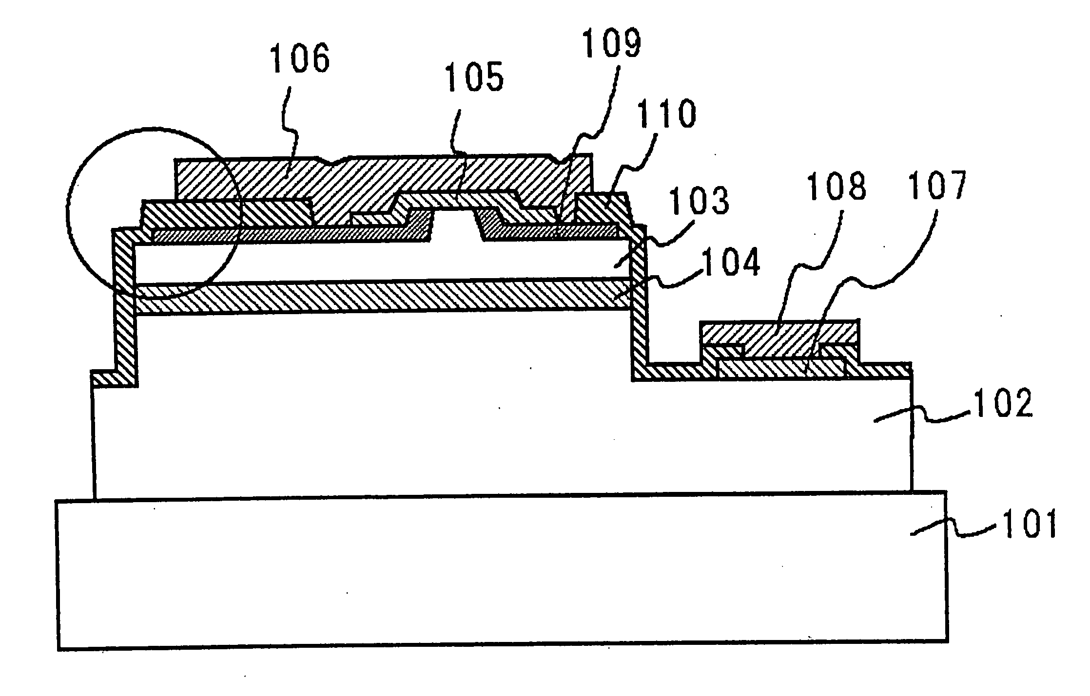
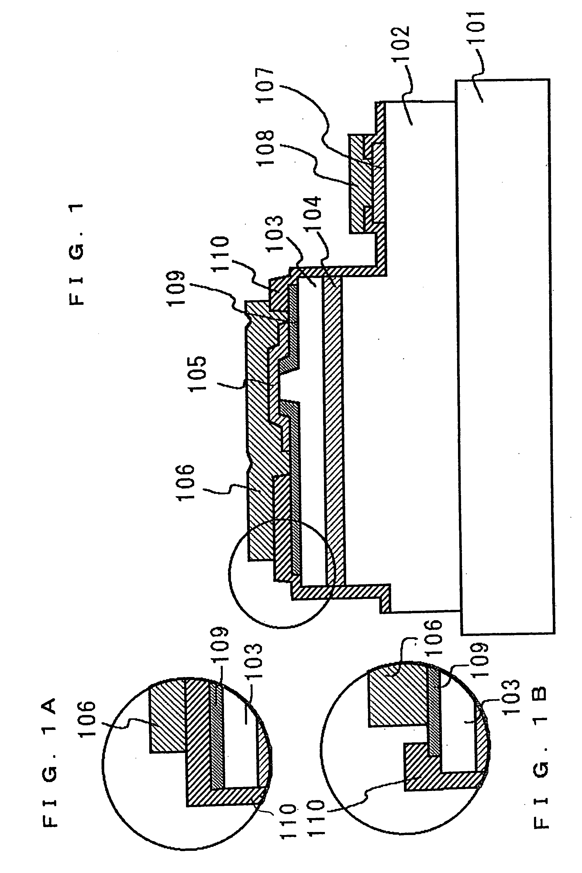
[0072]FIG. 1 shows a nitride semiconductor device according to a first embodiment. The nitride semiconductor device is a semiconductor laser diode (LD) including an n-type nitride semiconductor layer 102, an active layer 104, and a p-type nitride semiconductor layer 103 deposited in that order on a substrate 101. The p-type nitride semiconductor layer 103 has a ridge stripe. The ridge stripe is formed by partially etching the p-type nitride semiconductor layer or other processes to function as an effective refractive-index waveguide. Alternatively, the ridge stripe may be formed by partially etching a region from the p-type semiconductor layer to the n-type nitride semiconductor layer to function as a real refractive-index waveguide, or by the selective growth method. The ridge stripe is not necessarily formed in a mesa manner shape, in which the width of the stripe is gradually reduced upward. For example, it may be in a reversed mesa manner, in which the width is reduced downward,...
second embodiment
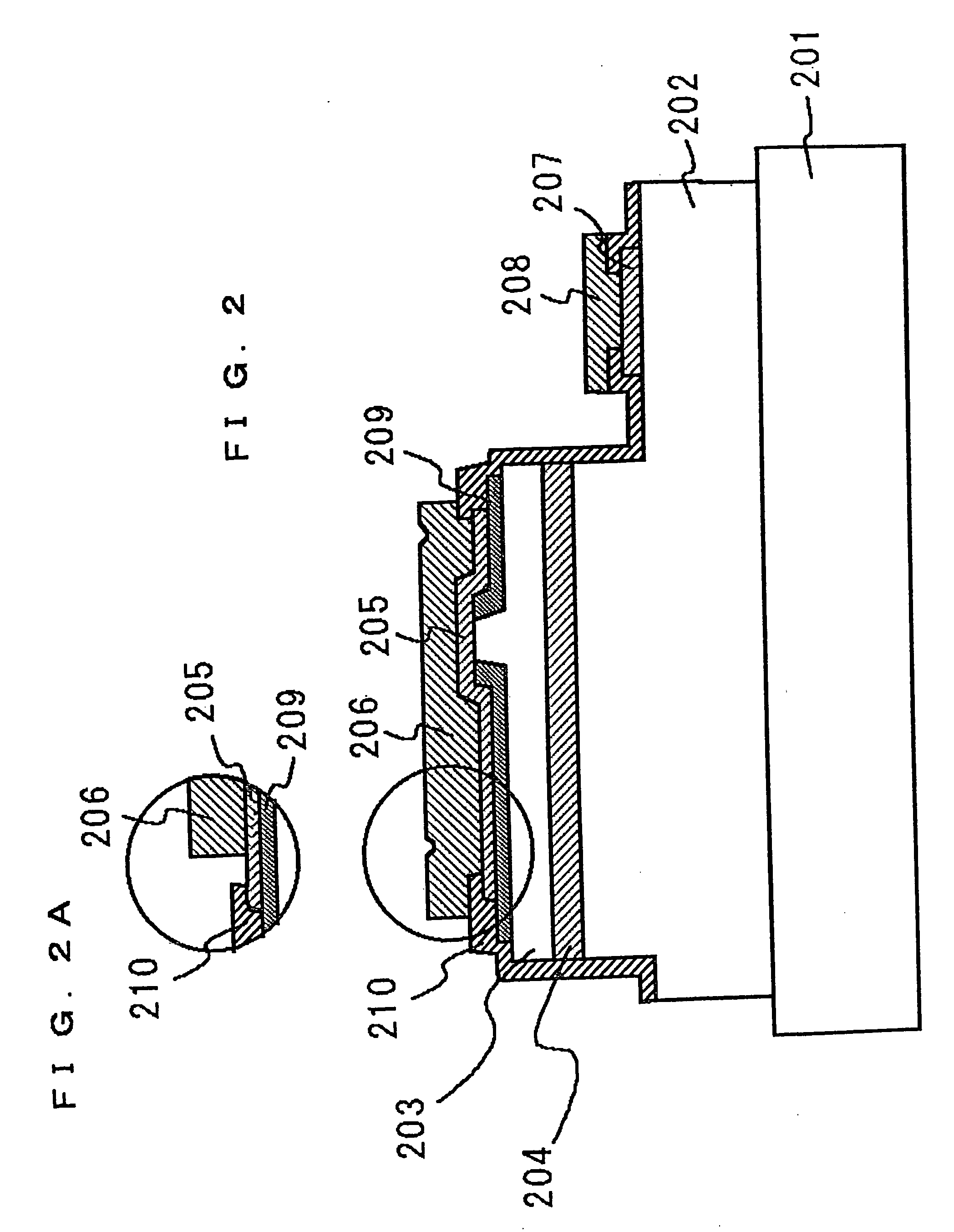
[0082]FIG. 2 shows a nitride semiconductor device according to a second embodiment of the present invention. The nitride semiconductor device is a semiconductor laser diode (LD) including an n-type nitride semiconductor layer 202, an active layer 204, and a p-type nitride semiconductor layer 203 deposited on a substrate 201, as in the first embodiment. The p-type nitride semiconductor layer 203 has a ridge stripe. A first p electrode 205 is formed so as to cover a wide region of a first insulating layer 209. A second insulating layer 210 is formed so as to overlap the first p electrode 205 in regions apart from the ridge stripe. A second p electrode 206 is formed on the first p electrode 205 and the second insulating layer 210. Hence, in second embodiment, the second p electrode 206 is not in contact with the first insulating layer 209. The light confinement in the waveguide region may be varied depending on the depth (height) of the ridge stripe of the first insulating layer 209, a...
third embodiment
[0084]FIG. 3 shows a nitride semiconductor device according to a third embodiment of the present invention. This nitride semiconductor device is a semiconductor laser diode (LD) including an n-type nitride semiconductor layer 302, an active layer 304, and a p-type nitride semiconductor layer 303 deposited on a substrate 301, as in the first embodiment. The p-type nitride semiconductor layer 303 has a ridge stripe. In the third embodiment, an adhesion layer 311 is provided between a second p electrode 306 and at least one of a first insulating layer 309 and a second insulating layer 310. The adhesion layer 311 increases the adhesion between the second p electrode 306 and the first insulating layer 309 or the second insulating layer 310, and is not placed on the upper surface of the ridge stripe, where a first p electrode 305 is joined to the second p electrode 306, or the vicinity of the upper surface.
[0085] The electrodes and insulating layers must have good adhesiveness not only t...
PUM
 Abstract
Description
Claims
Application Information
 - R&D
- Intellectual Property
- Life Sciences
- Materials
- Tech Scout
- Unparalleled Data Quality
- Higher Quality Content
- 60% Fewer Hallucinations
Browse by: Latest US Patents, China's latest patents, Technical Efficacy Thesaurus, Application Domain, Technology Topic, Popular Technical Reports.
© 2025 PatSnap. All rights reserved.Legal|Privacy policy|Modern Slavery Act Transparency Statement|Sitemap|About US| Contact US: help@patsnap.com


