Method in connection with permanent magnet synchronous machines

a permanent magnet synchronous machine and rotational speed technology, applied in the direction of electronic commutation motor control, motor/generator/converter stopper, dynamo-electric converter control, etc., can solve the problem of inaccuracy in determining the position angle, and achieve the effect of improving noise rejection, small speed and position estimation error, and excellent dynamic properties

Inactive Publication Date: 2006-05-04
ABB OY
View PDF9 Cites 29 Cited by
  • Summary
  • Abstract
  • Description
  • Claims
  • Application Information

AI Technical Summary

Benefits of technology

[0011] An advantage of the method of the invention is that it achieves smaller speed and position estimation error and better noise rejection...

Problems solved by technology

The problem associated with the prior art methods for determining the position angle is the inaccuracy especia...

Method used


Image

  • Method in connection with permanent magnet synchronous machines
  • Method in connection with permanent magnet synchronous machines
  • Method in connection with permanent magnet synchronous machines

Examples


Embodiment Construction

[0016] Adaptive Observer

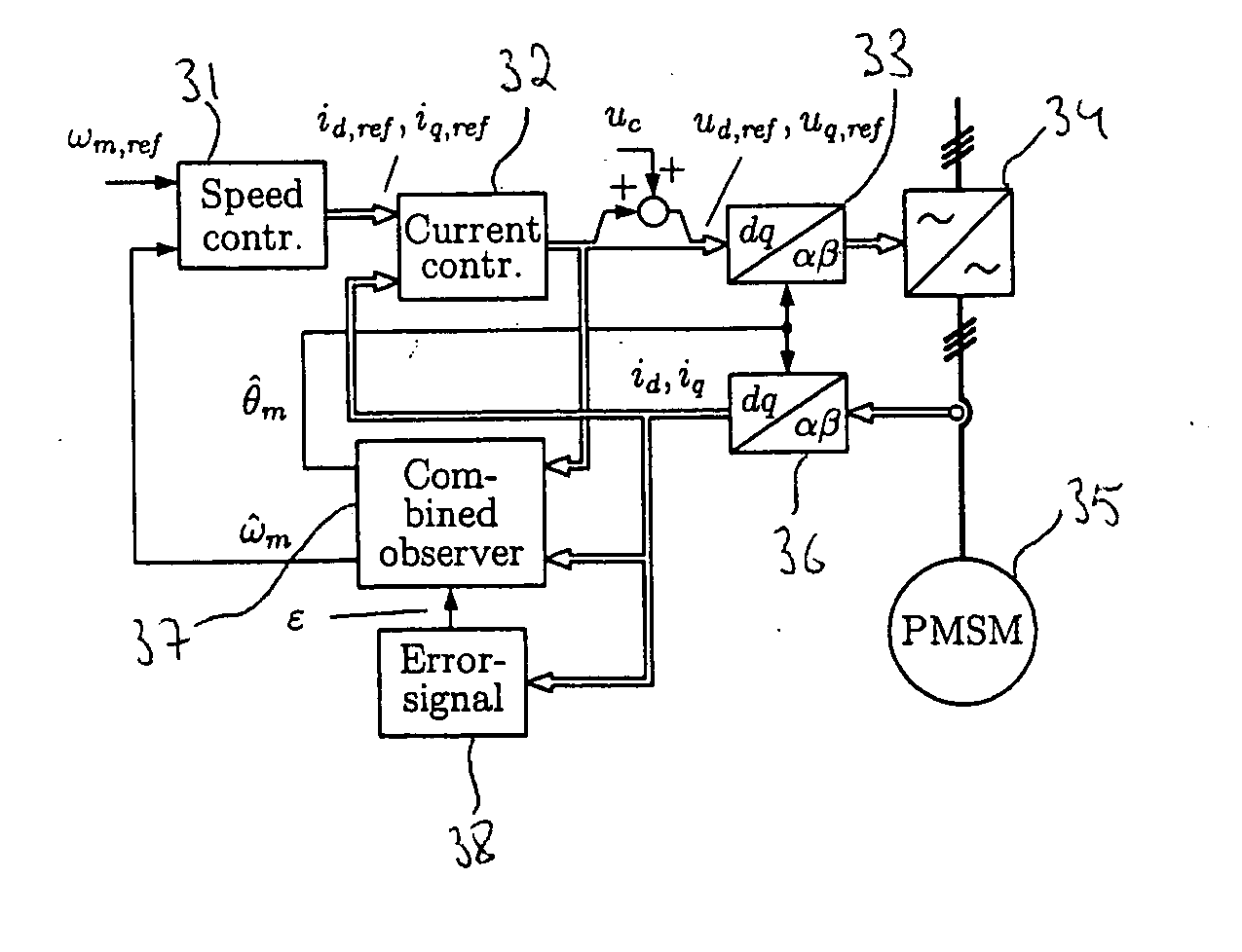
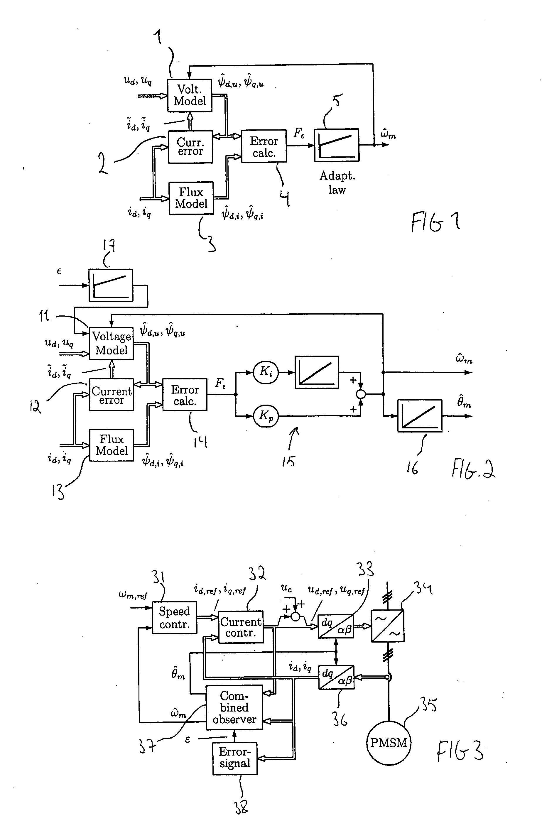
[0017] In an adaptive observer shown in FIG. 1, the rotor speed and position estimation is based on flux estimation error between two different models. A speed-adaptive flux observer has been developed for induction motors in [5]. For PMSMs, an adaptive observer has been disclosed in stator coordinates in [6], whereas the approach presented in this description is implemented in rotor coordinates. Estimates for the stator flux are calculated using both the voltage model and the flux model. The error of the two flux vectors is used to adapt the speed estimate so that the flux vectors correspond to each other. For the use in the flux and voltage models, the stator currents and voltages are measured and some parameters for these models are measured or identified.

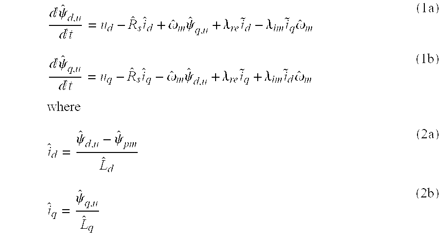
[0018] The stator flux components obtained by the voltage model in the rotor reference frame are ⅆψ^d,uⅆt=ud-R^s⁢i^d+ω^m⁢ψ^q,u+λre⁢i~d-λim⁢i~q⁢ω^m(1⁢a)ⅆψ^q,uⅆt=uq-R^s⁢i^q-ω^m⁢ψ^d,u+λre⁢i~q+λim⁢i~d⁢ω^m⁢...


PUM


Abstract

A method for sensorless estimation of rotor speed and position of a permanent magnet synchronous machine the method comprising the steps of calculating first stator flux vector estimate ({circumflex over (ψ)}d,i+j{circumflex over (ψ)}q,i) using the flux model and measured stator currents, calculating second stator flux vector estimate ({circumflex over (ψ)}d,u+j{circumflex over (ψ)}q,u) using the voltage model and measured stator voltages, comparing the directions of the first and second flux vectors to achieve a first error signal (Fε), using speed adaptation to achieve estimates for the rotor angular speed ({circumflex over (ω)}m) and angular position ({circumflex over (θ)}m) from the first error signal (Fε), injecting a known voltage signal (uc) to the stator voltage, detecting a current signal (iqc) from the stator current to form a second error (ε) signal, which is dependent on the estimation error of the rotor position, augmenting the voltage model by the second error signal (ε) to keep the first and second flux vector estimates aligned and so to correct the rotor angular speed ({circumflex over (ω)}m) and angular position ({circumflex over (θ)}m) estimates.

Description

FIELD OF THE INVENTION [0001] This invention relates to method for estimating the position angle and the rotational speed of a sensorless permanent magnet synchronous machine. BACKGROUND OF THE INVENTION [0002] Vector control of a permanent magnet synchronous motor (PMSM) requires accurate information of the rotor position. The simplest method to determine the required rotor position is to use a mechanical sensor. However, the sensor coupled to the shaft is a mechanical component liable to faults, which increases the price of a motor drive considerably. In addition, as the motor drive control is based on information obtained from the sensor, sensor breakage inevitably causes downtime in said motor drive. [0003] In sensorless control, the rotor speed and position are estimated without mechanical sensors either by a fundamental-excitation method or a high-frequency (HF) signal injection method. Fundamental-excitation methods are based on the dynamic model of the motor, while signal in...

Claims


Application Information

Patent Timeline
IPC IPC(8): H02P6/00
CPCH02P21/141H02P21/146H02P2203/11H02P2207/05H02P21/18
Inventor PIIPPO, ANTTI
Owner ABB OY
Why Eureka
Try Eureka