Common mode stabilization circuit for differential bus networks

a technology of differential bus network and common mode stabilization circuit, which is applied in the direction of pulse generator, pulse manipulation, pulse technique, etc., can solve the problems of radiated emissions, interference with various types of electronic equipment, cell phones and radios, and radiated emissions, so as to improve symmetry and minimize common modes

Active Publication Date: 2006-05-04
TEXAS INSTR INC
View PDF4 Cites 29 Cited by
  • Summary
  • Abstract
  • Description
  • Claims
  • Application Information

AI Technical Summary

Benefits of technology

[0017] The advantages include but are not limited to a differential bus network output driver that minimizes common-mode disturbance during bus transitions, but also a differential bus network that provides improved symmetry between its differential output signals and provides protection for its low voltage devices from voltage transients occurring on its output lines.

Problems solved by technology

Unfortunately, at this length, the CAN wire acts as an ideal antenna which is subject to automotive-type high voltage transients, as well as industrial-type transients, such as radiated emissions, electromagnetic interference (EMI) and electrostatic discharge (ESD).
In general, radiated emissions interfere with various types of electronic equipment, such as cell phones and radios or any other electronic device.
Furthermore, besides the ISO length requirement being the primary cause of radiated emissions, radiated emissions occur when there is no symmetry between the CAN signals, CANH and CANL.
If the CAN signals, CANH and CANL, are skewed in anyway from one another, a voltage differential for the CAN signal is created which results in radiated emissions.
However, in this configuration, these low voltage components cannot withstand high voltage conditions due to gate oxide integrity issues and drain-to-source breakdown voltage limitations.
High voltage components are not desirable for CAN applications due to their larger gate capacitances, and hence their slower operation.
These high voltage components also incur a considerable silicon area penalty.
Moreover, radiated emissions may stem from non-idealities that exist when the CAN wires transition from the dominant state to the recessive state.

Method used


Image

  • Common mode stabilization circuit for differential bus networks
  • Common mode stabilization circuit for differential bus networks
  • Common mode stabilization circuit for differential bus networks

Examples


Embodiment Construction

[0028] One or more exemplary implementations of the present invention will now be described with reference to the attached drawings, wherein like reference numerals are used to refer to like elements throughout. The various aspects of the invention are illustrated below in a differential bus network, although the invention and the appended claims are not limited to the illustrated examples.

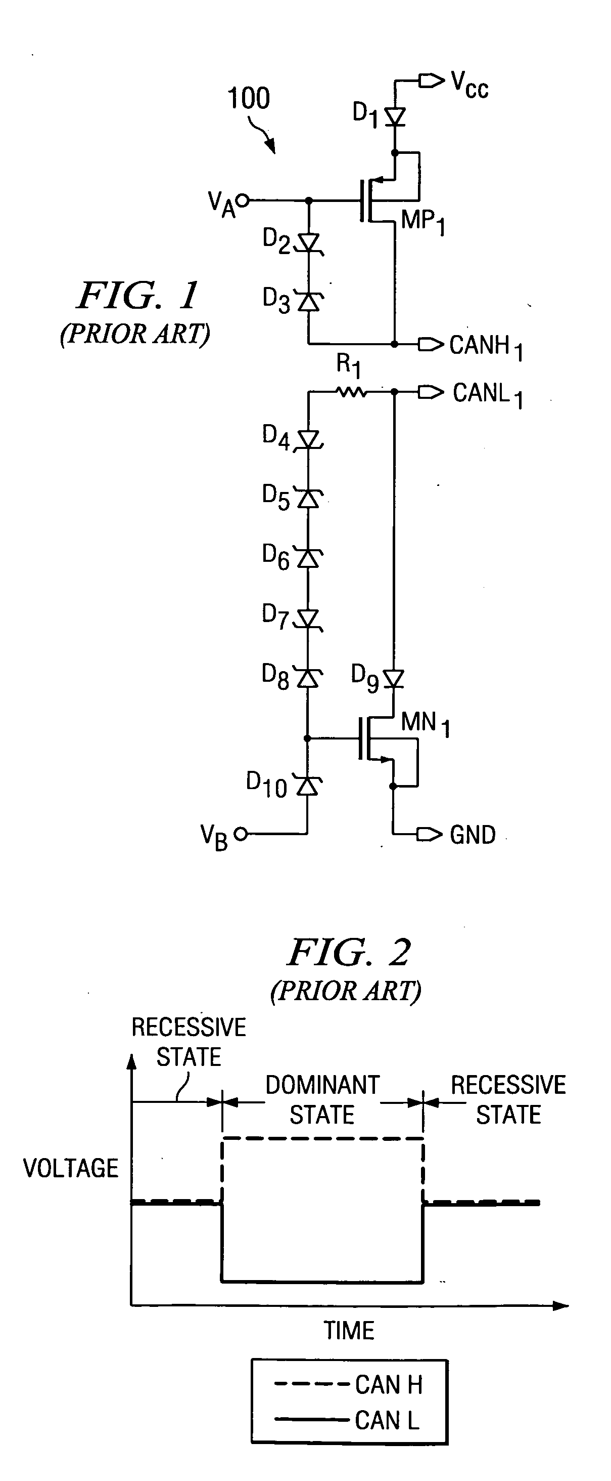
[0029] The present invention is best understood by comparison with the prior art. Hence, this detailed description begins with a discussion of known output driver of a differential bus network shown in FIG. 1.

[0030] A known output driver of a CAN transceiver is shown in FIG. 1. A signal to be transmitted, TxD, (not shown) is applied to wave shaping circuitry (not shown), wherein voltage references, VA and VB, are a derivative of this transmitted signal, TxD. The voltage references, VA and VB, are applied to the gate of transistors, MP1 and MN1, respectively. Diodes, D2 and D3, are coupled in ser...


PUM


Abstract

A differential bus network, in general, or a controller area network (CAN) driver, in particular, controls and minimizes the variation on the common-mode signal of the CAN bus. This CAN driver also provides improved symmetry between its differential output signals, CANH and CANL, and provides protection for its low voltage devices from voltage transients occurring on its output lines. The common-mode signal is sensed and buffered, then during the dominant to recessive transition, the bus signals are shorted to the buffered common mode voltage. Specifically, additional switches or transistors are used to pull the differential output signals, CANH and CANL, to the common mode signal VCM when the state of the CAN bus transitions from dominant to recessive. This improvement minimizes high frequency spikes in the common-mode signal and eliminates DC shifts during transitions of the state of the CAN bus. A driver system may include a plurality of CAN drivers are serially interconnected to form a driver system, wherein each downstream driver stage receives a time-delayed form of the digital input signal TxD, each stage providing a time-delayed contribution to the differential output signals of the overall driver system.

Description

FIELD OF THE INVENTION [0001] The present invention relates to differential bus networks and, more particularly, to an output driver for use in any differential bus network transceiver for employing low voltage components for high speed performance configured to handle high voltage transients. BACKGROUND OF THE INVENTION [0002] Differential bus networks include one or more data buses connecting subcircuits of a system as a means of providing signal transmission to internal and external subcircuits incorporated within the system. Differential bus networks are typically used in electronic communication systems, such as, automotive multiplex wiring and computer interfaces. In particular, differential bus networks may include differential bus drivers applicable to voltage mode interface standards, such as RS422, Controller Area Network (CAN), Automotive Multiplex Wiring System (Abus) and Vehicle Area Network (VAN). [0003] CAN systems are currently implemented as common networking system...

Claims


Application Information

Patent Timeline
Patent Type & Authority Applications(United States)
IPC IPC(8): H03B1/00
CPCH04L25/0284H04L25/085
Inventor PAULETTI, TIMOTHY P.CARPENTER, JOHN H. JR.CHEN, WAYNE TIEN-FENG
Owner TEXAS INSTR INC
Why Eureka
Try Eureka