Magnetic circuit having dual magnets, speaker and vibration generating apparatus using the same

a dual-magnet, vibration-generating apparatus technology, applied in the direction of transducer details, electrical transducers, electrical apparatus, etc., can solve the problems of lowering efficiency, not achieving uniform magnetic, non-uniform conformity according, etc., to prevent leakage of magnetic flux and improve linear response of vibration system

Inactive Publication Date: 2006-05-04
KIM SEONG BAE
View PDF4 Cites 35 Cited by
  • Summary
  • Abstract
  • Description
  • Claims
  • Application Information

AI Technical Summary

Benefits of technology

[0024] To solve the above problems, it is an object of the present invention to provide a magnetic circuit having a dual magnet of high-efficiency and low-distortion frequency characteristics and a speaker using the same, which includes first and second magnetic circuits respectively including a F-type magnet and a P-type magnet, to thereby improve a linear response of a vibration system, that is, straightforwardness of a voice coil by realization of uniform distribution of lines of magnetic force on opposing surfaces of a yoke forming the magnetic gap in the first magnetic circuit including the F-type magnet, and prevent leakage of a magnetic flux in a magnetic gap portion by a loop-shaped second magnetic circuit including the P-type magnet.

Problems solved by technology

As a result, the attractive and repulsive forces applied to the voice coil 4 which is inserted into the magnetic gap G between the opposing yoke surfaces cause non-uniformity according to the position of the voice coil 4.
However, the technical method disclosed in the Korean Laid-open Patent Publication 2004-82462 provides an effect of improving straightforwardness of the voice coil, but does not prevent a magnetic flux leakage phenomenon to be described later and lowering of an efficiency, and does not propose the whole countermeasure for a large allowance input for a high output and a scheme of increasing a magnetic flux density.
However, the magnetic circuit does not accomplish uniform magnetic flux distribution in the structure of the yoke opposing surfaces forming a magnetic gap portion, and thus does not solve straightforwardness of the voice coil.
However, it is difficult to compulsively mount the magnets of the identical polarity, and a dual magnet installed in the magnetic circuit does not increase a magnetic flux density in the magnetic gap but decreases performance of the magnets.
However, this does not provide a sufficient magnetic flux density appropriate for a high output speaker.
Also, in the case of using a large-scale annular magnet using Neodymium (Nd), it is difficult to assemble other components because of a strong magnetic force thereof.
Further, in the case of a sub-woofer having a large-output, large-diameter vibrating diaphragm, a structure of accurately adjusting vertical movement in a vibration system when a base band frequency signal is reproduced is not presented.
Accordingly, a frequency reproduction feature goes bad or the vibrating diaphragm may be damaged.
Also, heat generated from the voice coil and the magnet is not properly cooled, the feature of the sub-woofer deteriorates.
As described above, the conventional speaker magnetic circuit does not solve leakage of the magnetic flux, non-uniform distribution of the magnetic flux in the magnetic gap, and problems of a high efficiency, high output / high input and heat radiation.
By the way, since the conventional vertical exercise device has an eccentric weight on the rotational axis of the rotating motor, and thus a support plate is vibrated up and down when the eccentric weight is rotated, partial wear of bearings becomes severe due to the eccentricity, and noise is greatly generated.
Also, since the conventional vertical exercise device uses a rotating motor, it is difficult to provide a sufficient vibration force.
However, it is appropriate for users to feel three-dimensional vibration in correspondence to audio signals but a magnetic force for driving a vibrating diaphragm lacks for an aerobic exercise.
That is, since a magnetic force of a direct-current (DC) magnetic field using permanent magnets does not exceed 5000 Gauss at maximum in an ordinary limited magnitude, such a vibrator is not proper for a vibrating diaphragm driving mechanism for an aerobic exercise.

Method used


Image

  • Magnetic circuit having dual magnets, speaker and vibration generating apparatus using the same
  • Magnetic circuit having dual magnets, speaker and vibration generating apparatus using the same
  • Magnetic circuit having dual magnets, speaker and vibration generating apparatus using the same

Examples


Embodiment Construction

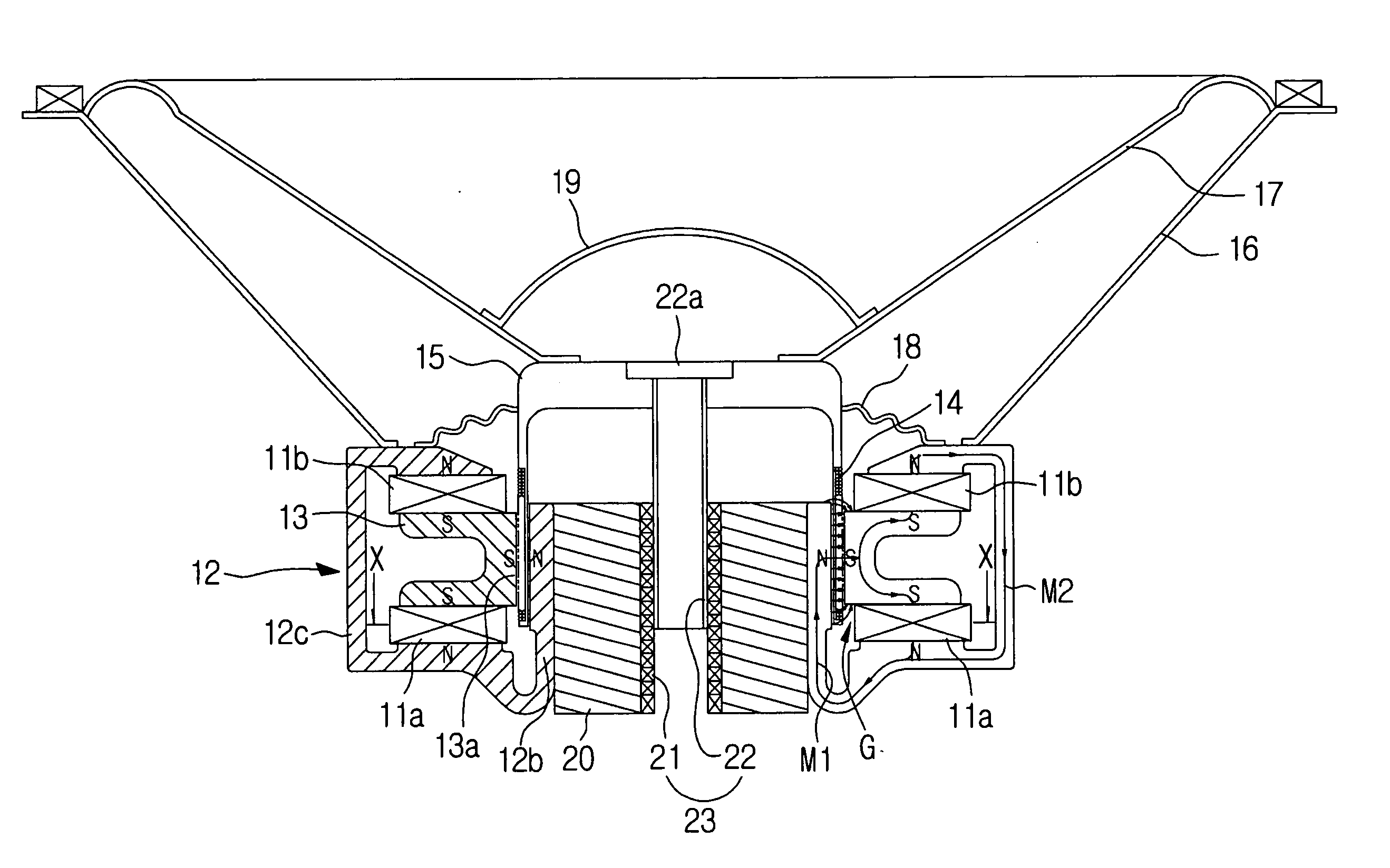
[0045] Hereinbelow, a magnetic circuit and a speaker using the same according to a preferred embodiment of the present invention will be described with reference to the accompanying drawings. Like reference numerals denote like elements through the following embodiments.

[0046] A cross-sectional view showing a high-efficiency, high output speaker having a dual magnet according to the present invention is shown in FIG. 2. A cross-sectional view cut along a line X-X of FIG. 2 is shown in FIG. 3.

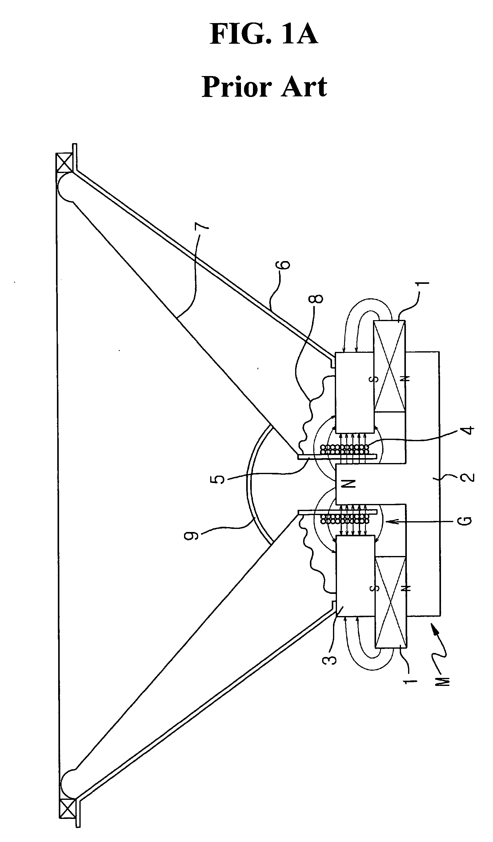
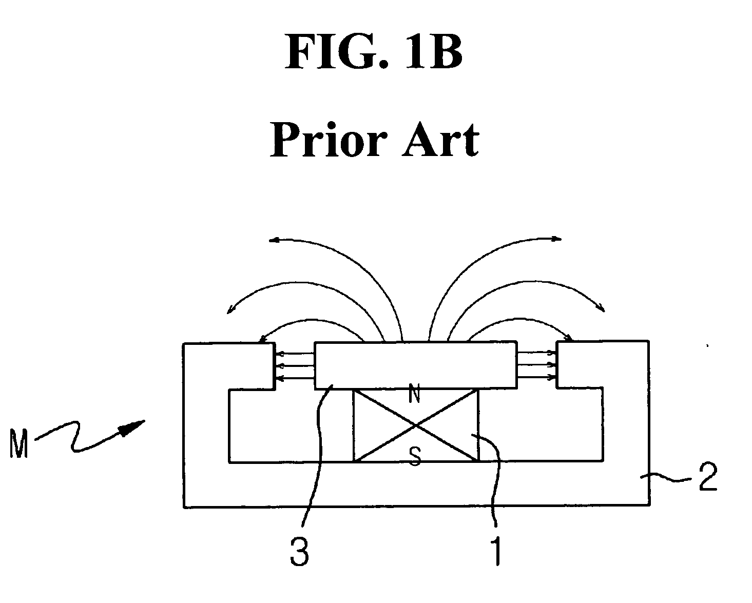
[0047] Referring to FIGS. 2 and 3, a speaker having a dual magnet according to an embodiment of the present invention includes first and second magnetic circuits M1 and M2 which include a F-type(in which a magnet is located externally in a magnetic circuit) magnet 11a and a P-type(in which a magnet is located internally in a magnetic circuit) magnet 11b, respectively, to thereby realize uniform distribution of lines of magnetic force on opposing surfaces 12 and 13 of a yoke forming a magnetic ...


PUM


Abstract

A magnetic circuit having a dual magnet, a speaker and a vibration generating apparatus using the same are provided. The magnetic circuit includes a magnetic gap having a small magnetic loss and an increasing magnetic flux density, in which a uniform distribution of a line of magnetic force can be realized on yoke surfaces facing each other. The speaker includes lower and upper magnets which are spaced so that mutually identical polarities oppose each other; a first yoke integrally having a loop-type circulating circuit portion extended from the lower magnet to the upper magnet and an extension portion which is extended perpendicularly upwards from the lower magnet; a second yoke which connects between the lower and upper magnets and forms a magnetic gap between the second yoke and the extension portion of the first yoke; a coil disposed in the magnetic gap and wound around a bobbin; a frame which is extended from the first yoke; a vibrating diaphragm generating an acoustic sound in correspondence to a drive signal; a damper limiting a vibration range of the bobbin; and a center cap covering the bobbin.

Description

BACKGROUND OR THE INVENTION [0001] 1. Field of the Invention [0002] The present invention relates to a magnetic circuit having a dual magnet, a speaker and a vibration generating apparatus using the same, and more particularly, to a magnetic circuit having a dual magnet, a speaker and a vibration generating apparatus using the same, in which a P-type magnet and a F-type magnet are included in a dual magnetic circuit, having a small magnetic loss and an increasing magnetic flux density, in a magnetic gap to thereby realize a uniform distribution of a line of magnetic force on yoke surfaces facing each other and forming the magnetic gap, and to thus have characteristics of high efficiency, high output, and low distortion frequency. [0003] 2. Description of the Related Art [0004] In general, acoustic reproduction devices are classified into a horn speaker, a system speaker which is used for a hi-fi audio system such as a component system, having a woofer, a midrange and a tweeter cover...

Claims


Application Information

Patent Timeline
Patent Type & Authority Applications(United States)
IPC IPC(8): H04R9/06
CPCH04R9/025H04R2209/022H04R2209/024
Inventor KIM, SEONG BAE
Owner KIM SEONG BAE
Why Eureka
Try Eureka