
Forming fabrics

Active Publication Date: 2006-05-11
ALBANY INT CORP
View PDF31 Cites 28 Cited by
  • Summary
  • Abstract
  • Description
  • Claims
  • Application Information

AI Technical Summary

Benefits of technology

[0025] According to an embodiment of the present invention, a fabric is provided which comprises a first layer having a plurality of machine direction (MD) yarns and cross-direction (CD) yarns and a second layer having a plurality of MD and CD yarns. The MD yarns and the CD yarns in the first layer and the second layer are monofilament yarns. A group of yarns including at least some of the CD yarns of the first layer and at least some of the CD yarns of the second layer have a first melting point temperature and the remaining yarns have one or more melting point temperatures each higher than the first melting point temperature. The fabric is heated to a predetermined temperature which is at least equal to the first melting point temperature yet lower than each of the one or more melting point temperatures of the remaining yarns. The CD yarns of the first layer of the group and the CD yarns of the second layer of the group which are in contact with each other or in close proximity to each other and which have a first melting point temperature prior to being heated, bond with each other after being heated to the predetermined temperature. Further, the diameter and count of the CD yarns in the first layer and the second layer may be larger than the diameter and count of the MD yarns in the first layer and the second layer to increase the probability of bonding.

Problems solved by technology

If drainage occurs too rapidly or too slowly, the sheet quality and machine efficiency suffers.
A fine fabric having small diameter yarns and a high number of yarns in both the MD and CD directions may provide the desired paper surface and fiber support properties, but such a design may lack the desired stability and wear resistance resulting in a shorter useful fabric life.
However, a shortcoming of laminated fabrics is the relative slippage between the layers of the fabric.
This slippage and relative fabric movement ultimately may lead to fabric delamination.
This relative movement may lead to fatigue and wear of the binder monofilament due to repeated deflection back and forth within the structure.
Eventually, the binder monofilament may fail and allow the top and bottom fabrics to separate (delaminate) from each other.
Further, the lamination of the fabric should not interfere with drainage of the structure such that the sheet of paper formed on the structure has an undesirable mark.
In addition, forming fabrics, especially thin fabrics, may also be prone to wrinkling or folding.
Wrinkling or folding may be due to high “sleaziness” of fabric construction.
High sleaziness means that the fabric does not have the necessary dimensional stability or CD stiffness to remain flat during operation.
Low seam strength can cause fabrics to prematurely tear during operation.

Method used


Image

  • Forming fabrics
  • Forming fabrics
  • Forming fabrics

Examples


Embodiment Construction

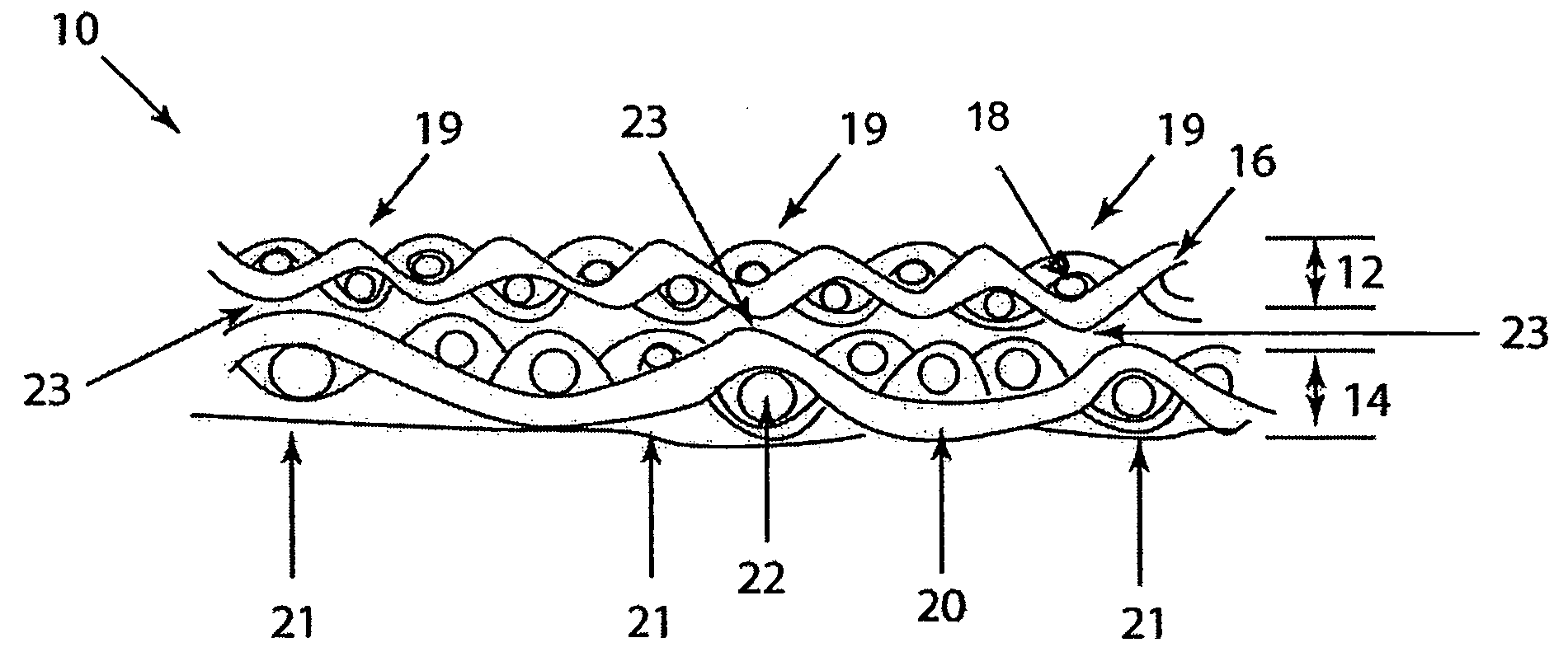
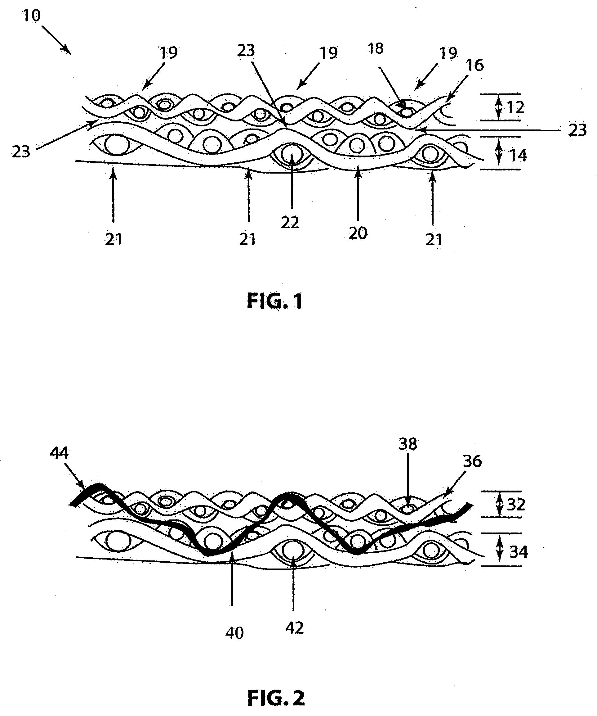
[0036] The present invention relates to a fabric which may be usable in the forming section of a papermaking machine. An embodiment of the present invention will be described in the context of a laminated forming fabric. However, it should be noted that the invention is not limited thereto but may be applicable to other fabrics such as forming fabrics having a single layer, single layer support shute, double layer, double layer support shute, triple stacked shute, triple layer with paired weft or warp binders, warp bound triple layer, shute bound triple layer or combined warp / shute bound triple layer.

[0037] Such a laminated fabric may include a first (upper) layer and a second (lower) layer in which each of the first and second layers has a system or plurality of interwoven machine-direction (MD) yarns and cross-machine direction (CD) yarns. The first layer may be a paper side or faceside layer upon which the cellulosic paper / fiber slurry is deposited during the papermaking process...


PUM

PropertyMeasurementUnit
Temperatureaaaaaaaaaa
Timeaaaaaaaaaa

Abstract

A papermaker's fabric for use as a forming fabric. The fabric may include bondable or meltable monofilament yarns which may be formed from materials that retain substantial strength and tenacity after thermal treatment. Further, the remaining yarns in the forming fabric may be formed from materials that have a higher melting temperature than the monofilament material that will be thermally bonded or melted.

Description

BACKGROUND OF THE INVENTION [0001] 1. Field of the Invention [0002] The present invention relates to the papermaking arts. More specifically, the present invention relates to fabrics, such as forming fabrics, for use with a papermaking machine. [0003] 2. Description of the Prior Art [0004] During the papermaking process, a cellulosic fibrous web is formed by depositing a fibrous slurry, that is, an aqueous dispersion of cellulose fibers, onto a moving forming fabric in the forming section of a paper machine. A large amount of water is, drained from the slurry through the forming fabric, leaving the cellulosic fibrous web on the surface of the forming fabric. [0005] The newly formed cellulosic fibrous web proceeds from the forming section to a press section, which includes a series of press nips. The cellulosic fibrous web passes through the press nips supported by a press fabric, or, as is often the case, between two such press fabrics. In the press nips, the cellulosic fibrous web ...

Claims


Application Information

Patent Timeline
IPC IPC(8): D03D25/00D21F1/00
CPCD21F1/0045D21F1/0027Y10S162/903Y10T442/3976Y10T442/3203Y10T442/3228Y10T442/326Y10T442/3211D21F1/00
Inventor EAGLES, DANA
Owner ALBANY INT CORP
Features
  • Generate Ideas
  • Intellectual Property
  • Life Sciences
  • Materials
  • Tech Scout
  • Unparalleled Data Quality
  • Higher Quality Content
  • 60% Fewer Hallucinations
Learn More