Tin alloy electroplating system

a technology of tin alloy and electroplating system, which is applied in the field of plating a tin alloy, can solve the problems of tin plating suffering from a significant drawback, undesirable formation of spontaneous latent whisker, and ductile finish that can scratch or mar easily, so as to reduce the number of latent whiskering, and reduce the effect of disposal, environmental and health concerns

Inactive Publication Date: 2006-05-11
TASKEM
View PDF16 Cites 48 Cited by
  • Summary
  • Abstract
  • Description
  • Claims
  • Application Information

AI Technical Summary

Benefits of technology

[0005] The subject invention involves plating tin alloys while mitigating immersion plating of the alloying metal(s) that consequently minimizes latent whiskering. The tin alloys alleviate disposal, environmental, and health concerns since they are lead free. The tin alloy plating system permits the employment of working tin anodes without the danger of immersion plating of the alloy material thereon. Generally speaking, the tin alloy plating system permits the use of complexing agents that are not toxic further alleviating disposal, environmental, and health concerns associated with metal plating systems. Since working tin anodes may be employed as a source of tin in the tin alloy plating systems, significant cost reductions are achieved compared to plating systems that use liquid based tin salts as a tin source. The resultant tin alloys formed in accordance with the subject invention have desirable characteristics including one or more of lack of latent whiskering, relatively high tin content, lead free alloys, excellent solderability, excellent lubricity, excellent electrical conductivity, corrosion resistance, excellent leveling, excellent ductility, lack of pinholes, and controllable thickness.

Problems solved by technology

While tin does not tarnish easily, tin is a soft, ductile finish that can scratch or mar easily.
Unfortunately, tin plating suffers from a significant drawback, the undesirable formation of spontaneous latent whiskers.
In some applications using tin plating, whiskers are not functionally noticed and therefore harmless.
However, in other applications, such as closely spaced electronic circuits, whiskers undermine the operational function of devices employing a tin plating product.
Due to disposal, environmental, and health concerns, deposits that contain lead, as well as the general use of lead, are no longer desirable.

Method used


Image

  • Tin alloy electroplating system
  • Tin alloy electroplating system
  • Tin alloy electroplating system

Examples


Embodiment Construction

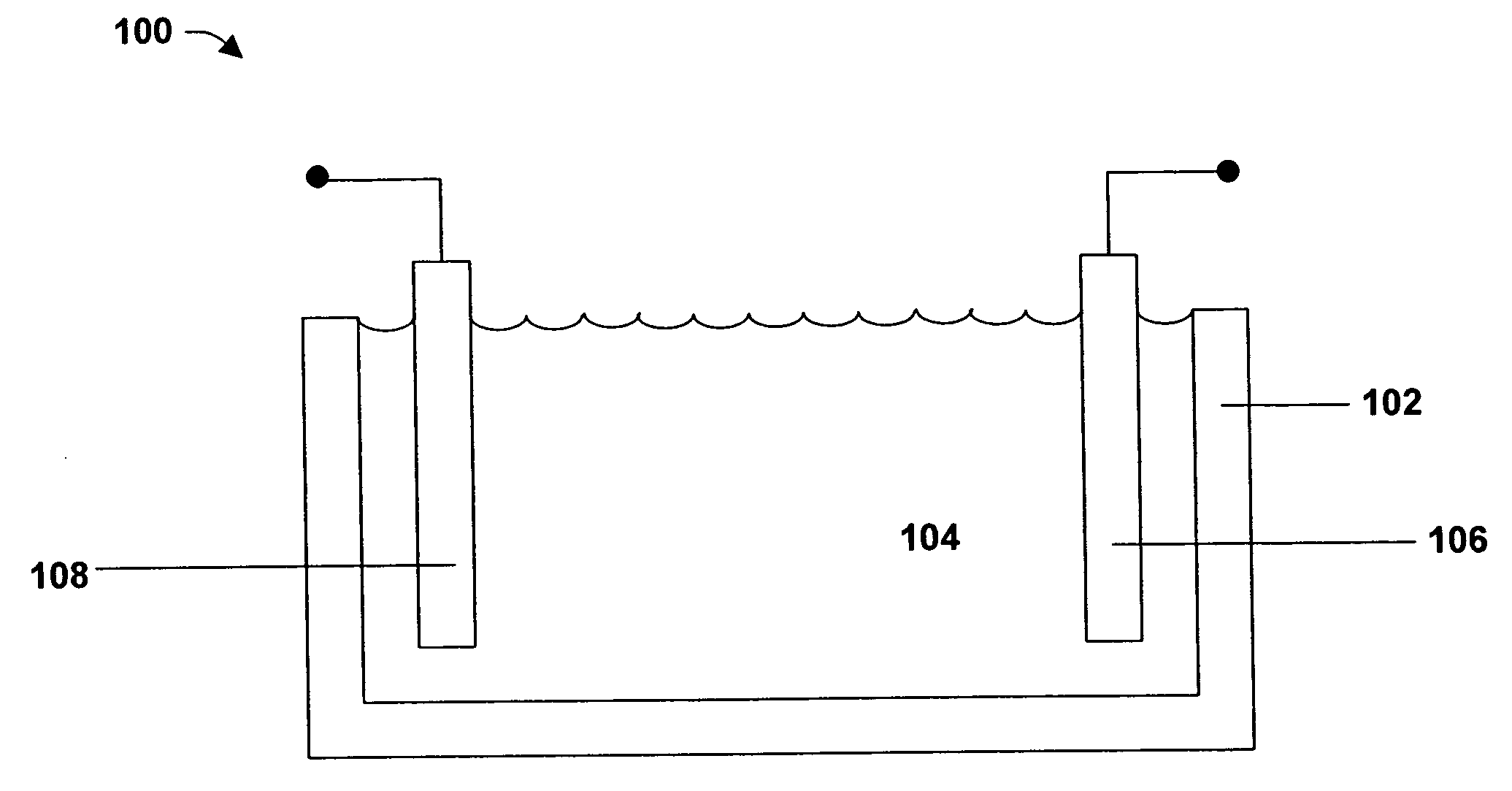
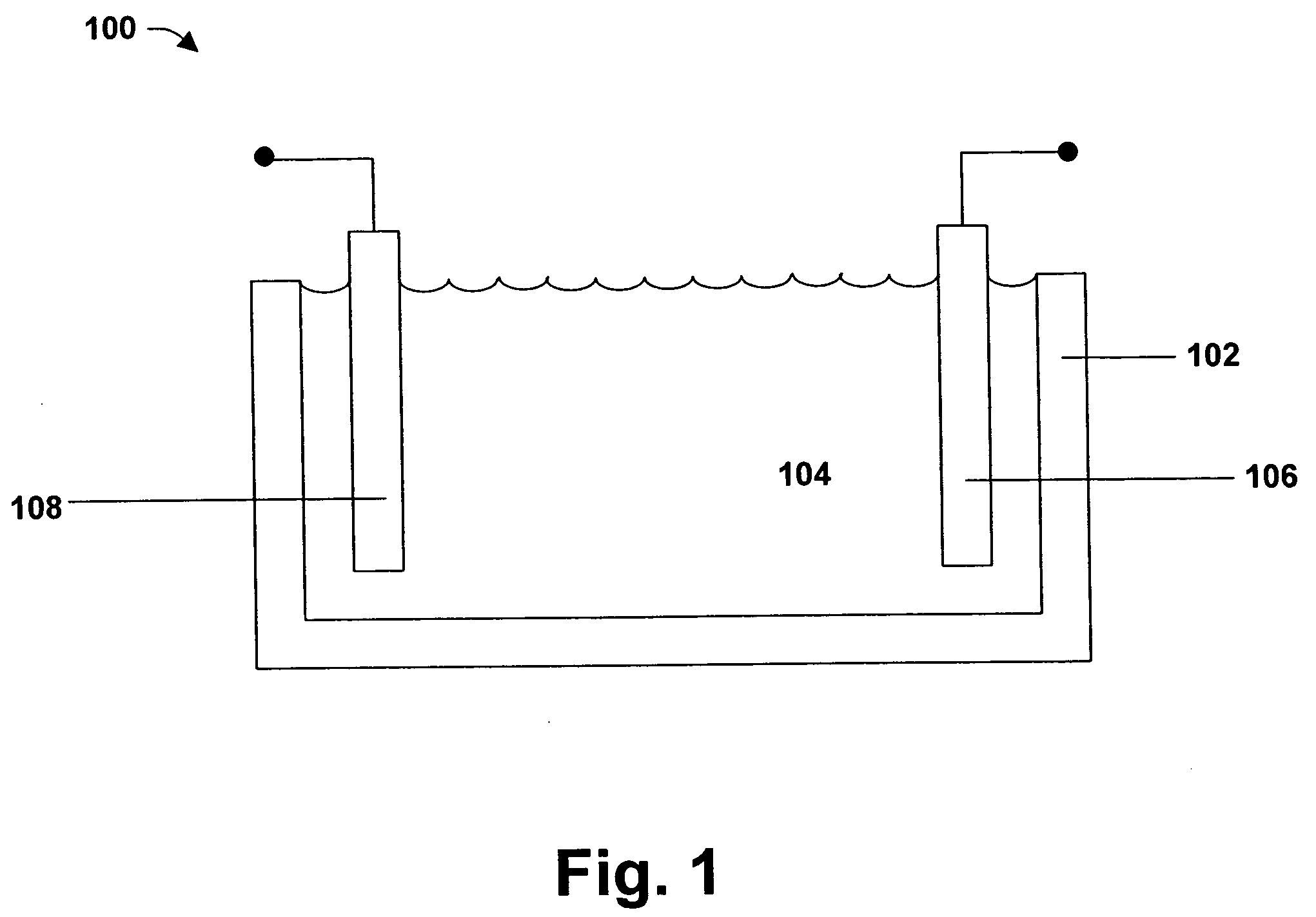
[0011] The subject invention can be employed for tin alloy electroplating. Generally speaking, electroplating involves metal in ionic form migrating in solution from a positive to a negative electrode. An electrical current passing through the solution causes substrates at the cathode to be coated by the metal (tin and alloy metal(s)) in solution. That is, in most embodiments, the substrate to be plated is the cathode.

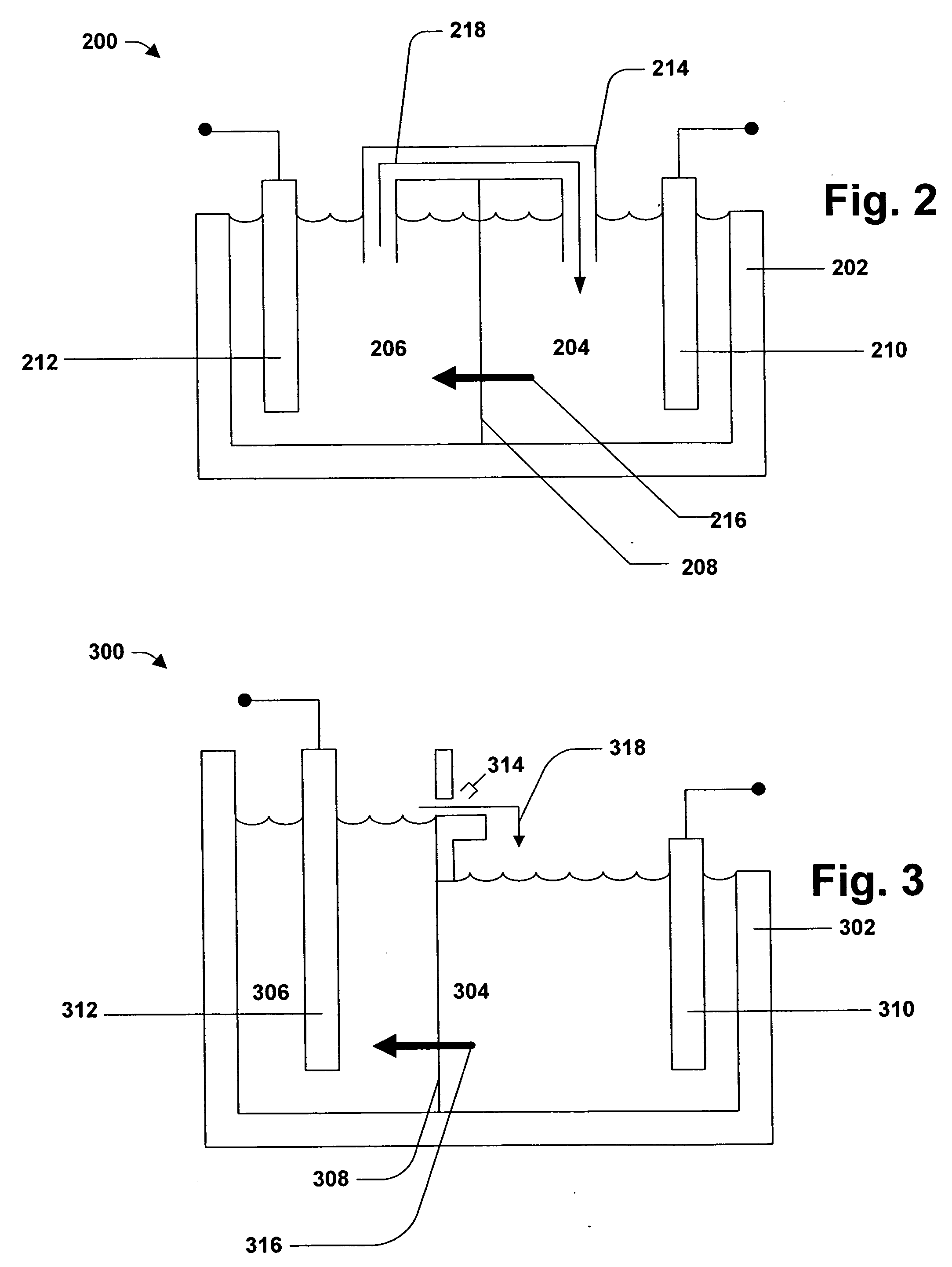
[0012] The electroplating bath or catholyte and anolyte (for simplicity, the term electroplating bath is used to encompass single compartment and multiple compartment systems, multiple compartment systems including at least one catholyte and at least one anolyte) are aqueous solutions. In this connection, the electroplating bath contains water. However, the electroplating bath may optionally contain one or more co-solvents. Such co-solvents include water-miscible solvents such as alcohols, glycols, alkoxy alkanols, ketones, and various other aprotic solvents. Specific...


PUM

PropertyMeasurementUnit
diameteraaaaaaaaaa
diameteraaaaaaaaaa
current carrying capacityaaaaaaaaaa

Abstract

Disclosed are systems and methods of plating a tin alloy in an efficient, economical, and environmentally friendly manner. The system for plating a tin alloy contains an electrochemical cell containing an anode, the cathode, and an electroplating bath. The electroplating bath contains water, an acid, at least one nitrogen-containing heterocyclic complexing agent, an ionic alloy metal, and ionic tin. The methods involve applying a current to the electroplating bath whereby a tin alloy forms on the cathode.

Description

FIELD OF THE INVENTION [0001] The subject invention generally relates to plating a tin alloy on a substrate while mitigating immersion plating of the alloying metal(s). In particular, the subject invention relates to systems and methods for electroplating tin alloys using a complexing agent to mitigate the immersion plating. BACKGROUND OF THE INVENTION [0002] Tin plating is known. Tin has many desirable attributes as a plated finish including solderability, lubricity, good electrical conductivity, and corrosion resistance. Tin is a silver-colored, ductile metal whose major application is to impart solderability to otherwise unsolderable base metals. Tin has generally good covering characteristics over a wide range of shapes. While tin does not tarnish easily, tin is a soft, ductile finish that can scratch or mar easily. Tin is reported to be non-toxic and non-carcinogenic and thus is approved for food container and food contact applications. [0003] Unfortunately, tin plating suffers...

Claims


Application Information

Patent Timeline
Patent Type & Authority Applications(United States)
IPC IPC(8): C25D3/58C25D3/60
CPCC25D3/56C25D3/60
Inventor BOKISA, GEORGEECKLES, WILLIAM E.
Owner TASKEM
Why Eureka
Try Eureka