Fuel cell system

a fuel cell and system technology, applied in the field of fuel cell systems, can solve the problem of insufficient optimal air stream generated by the compressor, and achieve the effect of enhancing the removal of water from the cathode spa

Active Publication Date: 2006-05-11
AIRBUS OPERATIONS GMBH
View PDF11 Cites 11 Cited by
  • Summary
  • Abstract
  • Description
  • Claims
  • Application Information

AI Technical Summary

Benefits of technology

[0027] Thus, the removal of water from the cathode space may thus be further enhanced.

Problems solved by technology

In order to prevent oversaturation by the generated water on the cathode side, which oversaturation would be disadvantageous for implementation, and in this way achieve an effective water production rate, the water must be continuously removed in the form of water vapour and water droplets.
Often the air stream generated by the compressor is insufficient for optimal removal of the water generated on the cathode side.

Method used


Image

  • Fuel cell system
  • Fuel cell system
  • Fuel cell system

Examples


Embodiment Construction

[0036] In the following description of the figures the same reference signs are used for identical or similar elements.

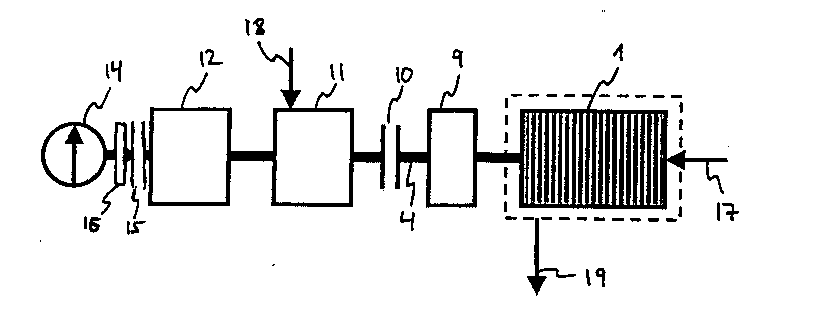
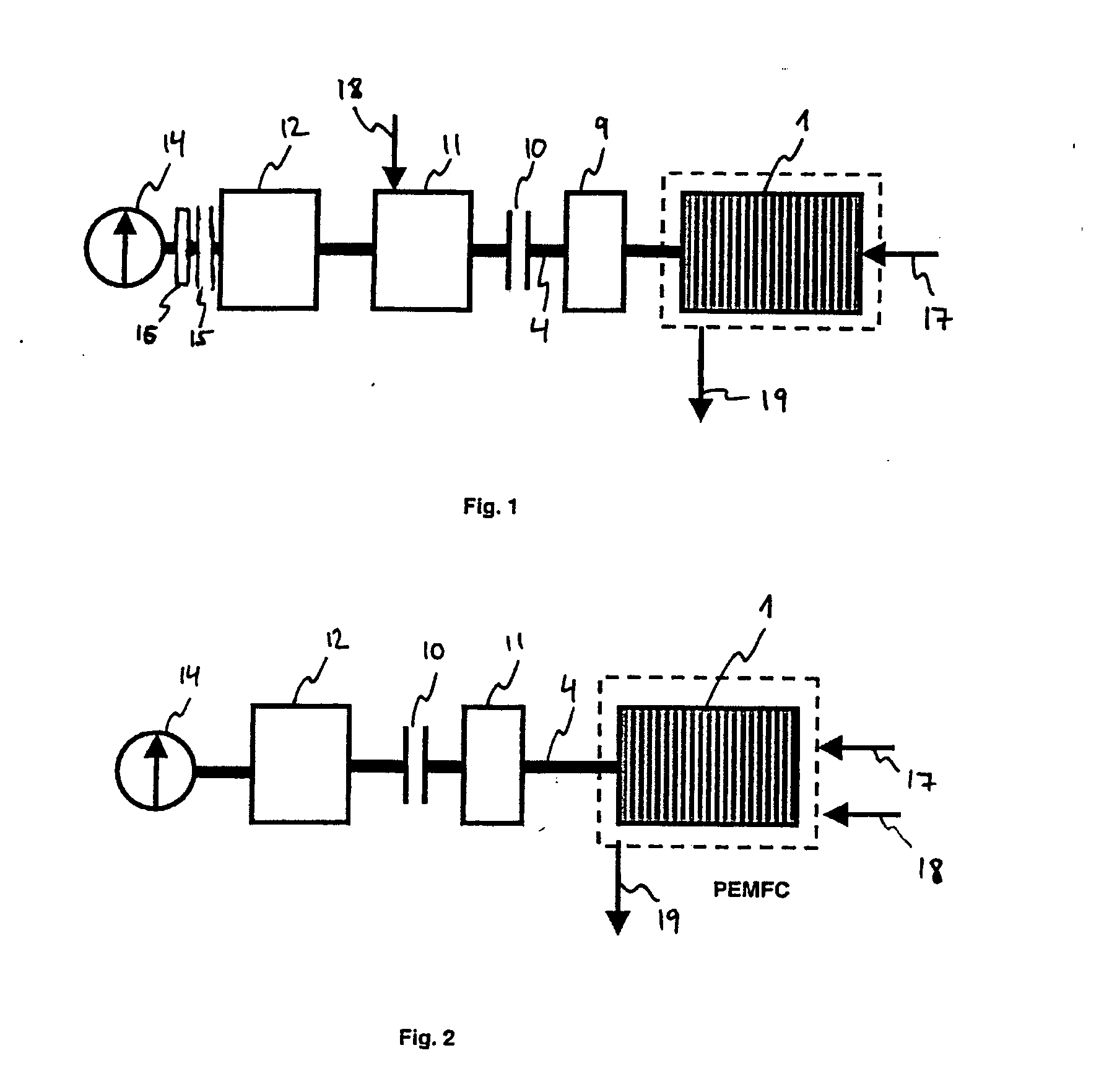
[0037]FIG. 1 shows a first diagrammatic view of a fuel cell system according to an embodiment of the present invention. As shown in FIG. 1, the fuel cell system comprises a proton exchange membrane fuel cell (PEMFC) 1, an electric motor 12, a compressor 11, a clutch 10, a torque converter 9 and a pump 14.

[0038] By way of a corresponding line, hydrogen 17 is fed to the fuel cell 1, and by way of a corresponding other line, humid air 19 is removed from the fuel cell 1. In this arrangement, the feeding in of hydrogen 17 is by way of a hollow shaft (not shown in FIG. 1) which forms part of a main shaft 4. The hydrogen is then fed to an anode (not shown in FIG. 1) of the fuel cell 1 so that an electrochemical reaction within the fuel cell can take place, by way of which reaction electrical energy and water are generated.

[0039] The water that arises in the cathode of t...


PUM

PropertyMeasurementUnit
electrical energyaaaaaaaaaa
mechanical energyaaaaaaaaaa
energyaaaaaaaaaa

Abstract

For operation, PEMFCs require among other things a compressor for the cathode air, and a system for removing the water which is generated on the cathode side as a result of the electrochemical reaction. According to an embodiment of the present invention the removal of water is supported in that the fuel cell is made to rotate by way of an electric motor so that the water contained in the cathodes of the fuel cell can be extracted by centrifugal force. To this effect the air channels on the cathode side are arranged so as to extend radially or in a spiral shape from the inside towards the outside. In this way the efficiency of the fuel cell can be significantly improved.

Description

CROSS-REFERENCE TO RELATED APPLICATIONS [0001] This application claims the benefit of the filing date of U.S. Provisional Patent Application No. 60 / 609,969 filed Sep. 15, 2004, the disclosure of which is hereby incorporated herein by reference.BACKGROUND OF THE INVENTION [0002] Fuel cells, in particular so-called proton exchange membrane fuel cells (PEMFCs) require for operation, among other things, a compressor for the cathode air, and a system for letting off the water generated on the cathode side by electrochemical reaction. In order to prevent oversaturation by the generated water on the cathode side, which oversaturation would be disadvantageous for implementation, and in this way achieve an effective water production rate, the water must be continuously removed in the form of water vapour and water droplets. Often the air stream generated by the compressor is insufficient for optimal removal of the water generated on the cathode side. [0003] There may be a need to provide an ...

Claims


Application Information

Patent Timeline
Patent Type & Authority Applications(United States)
IPC IPC(8): H01M8/02H01M8/04
CPCH01M8/00H01M8/004H01M8/0258H01M8/0267H01M8/04007H01M8/04059H01M8/04089H01M8/04111H01M8/04156H01M8/04291H01M8/2475H01M2008/1095H01M2250/20Y02T90/32Y02E60/50Y02T90/40
Inventor HOFFJANN, CLAUSSCHULDZIG, HANSGEORGHEINRICH, HANS-JUERGEN
Owner AIRBUS OPERATIONS GMBH
Why Eureka
Try Eureka