Method for removing water molecules from vacuum chamber, program for executing the method, and storage medium storing the program

a vacuum chamber and water molecules technology, applied in the direction of dispersed particle separation, separation processes, fluorine, etc., can solve the problems of increasing the time required to reach the required vacuum, reducing the efficiency of a processing apparatus, increasing the surface resistance of wafers, etc., to achieve efficient removal of water molecules, accelerate the removal of water molecules in the chamber, and efficiently remove water molecules

Active Publication Date: 2006-09-21
TOKYO ELECTRON LTD
View PDF4 Cites 1 Cited by
  • Summary
  • Abstract
  • Description
  • Claims
  • Application Information

AI Technical Summary

Benefits of technology

[0018] Accordingly, The reduction of water molecules is accelerated in the vacuum chamber and, further, the reduced water molecules can be exhausted as acid, accelerating the removal of water molecules in the vacuum chamber.
[0019] In the method for removing the water molecules from the vacuum chamber, the reduction gas may be carbon monoxide and the halogen-based gas may be carbon fluoride. Accordingly, the reduction of water molecules is further accelerated in the vacuum chamber, thereby allowing an efficient removal of water molecules from the vacuum chamber. Therefore, the removal of water molecules in the chamber can be accelerated.
[0020] In the method for removing the water molecules from the vacuum chamber, the reduction gas may be carbon monoxide and the halogen-based gas may be chlorine. Accordingly, the reduction of water molecules is further accelerated in the vacuum chamber, thereby efficiently removing water molecules from the vacuum chamber. Therefore, the removal of water molecules in the chamber can be accelerated.
[0021] The method for removing the water molecules from the vacuum chamber further includes the steps of measuring an amount of water molecules present inside the vacuum chamber; and determining whether or not the measured amount of water molecules is greater than or equal to a threshold value, wherein if the measured amount of water molecules is greater than or equal to the threshold value, the water molecule removal gas is introduced into the vacuum chamber in the introducing step. Accordingly, the water molecule removal processing in the vacuum chamber can be automatized. Thus, it is possible to reduce a downtime of an object processing apparatus including the vacuum chamber.
[0022] In the method for removing the water molecules from the vacuum chamber, the process may be an etching process carried out on the target object. Accordingly, it is possible to resolve an etching rate difference between object lots.
[0023] In the method for removing the water molecules from the vacuum chamber, the process may be a transfer process for transferring the target object. Accordingly, it is possible to prevent water molecules from being attached to the target object when it is transferred.

Problems solved by technology

The large amount of water molecules may cause the following problems:
1) To create a vacuum inside the chamber, the inside thereof must be exhausted, and the presence of the water molecules therein increases the time required to reach the required vacuum and reduces an efficiency of a processing apparatus;
2) During a metal film forming on a wafer in a chamber of a CVD apparatus, the presence of water molecules inside the chamber may cause a number of abnormalities such as forming of an oxide film, peeling of film layers from the wafer surface and increasing of wafer surface resistance;
5) An abnormal discharge occurring due to the presence of water molecules inside the chamber may damage the wafer and facilitate a generation of the peeled particles.
In the technology, however, HCl, BCl3, DCP and DMP do not readily react with water molecules.
Thus, all of the water molecules emitted in form of an out gas from pores in the alumite cannot be processed, and as a result, although HCl, BCl3, DCP and DMP are introduced in the chamber, it is difficult to accelerate the removal of water molecules in the chamber (etcher).

Method used


Image

  • Method for removing water molecules from vacuum chamber, program for executing the method, and storage medium storing the program
  • Method for removing water molecules from vacuum chamber, program for executing the method, and storage medium storing the program
  • Method for removing water molecules from vacuum chamber, program for executing the method, and storage medium storing the program

Examples


Embodiment Construction

[0030] A preferred embodiment of the present invention will now be described with reference to the accompanying drawings.

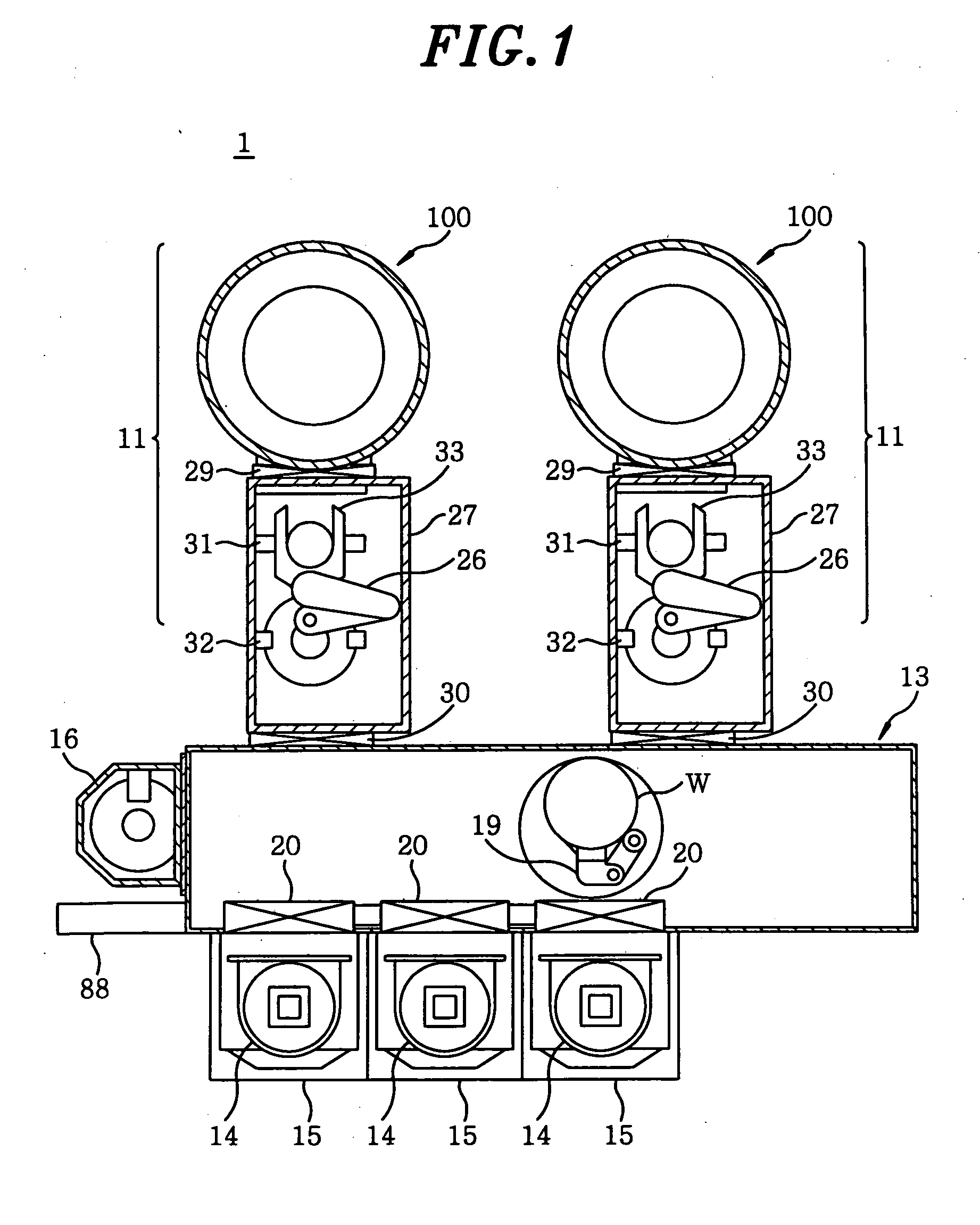
[0031]FIG. 1 is a cross sectional view showing a schematic configuration of a substrate processing apparatus including a plasma processing apparatus formed of a vacuum chamber in accordance with the preferred embodiment of the present invention.

[0032] The substrate processing apparatus 1 shown in FIG. 1 includes two process ships 11 for carrying out a reactive ion etching (RIE) process on a wafer for semiconductor devices (hereinafter, simply referred to as a “wafer”) W; and a loader module 13 that is a rectangular in shape and functions as a common transfer chamber to which the two process ships 11 are connected.

[0033] In addition to the process ships 11, connected to the loader module 13 are three FOUP mounting tables 15, each one mounting thereon a FOUP (Front Opening Unified Pod) 14 serving as a container for accommodating twenty-five wafers W; and an orien...


PUM

PropertyMeasurementUnit
diameteraaaaaaaaaa
diameteraaaaaaaaaa
temperatureaaaaaaaaaa

Abstract

A method for removing water molecules from a vacuum chamber for carrying out a process on a target object in vacuum includes the steps of introducing into the vacuum chamber a water molecule removal gas including at least a reduction gas which reduces the water molecules to produce hydrogen molecules and a halogen-based gas which reacts with the produced hydrogen molecules to produce acid, exhausting gases in the vacuum chamber measuring an amount of water molecules present inside the vacuum chamber, and determining whether or not the measured amount of water molecules is greater than or equal to a threshold value, wherein if the measured amount of water molecules is greater than or equal to the threshold value, the water molecule removal gas is introduced into the vacuum chamber in the introducing step.

Description

CROSS-REFERENCE TO RELATED APPLICATIONS [0001] This document claims priority to Japanese Patent Application Number 2005-79165, filed Mar. 18, 2005 and U.S. Provisional Application No. 60 / 666,717, filed Mar. 31, 2005, the entire content of which are hereby incorporated by reference.FIELD OF THE INVENTION [0002] The present invention relates to a method for removing water molecules from a vacuum chamber, a program for executing the method, and a storage medium storing the program. BACKGROUND OF THE INVENTION [0003] Conventionally, a plasma processing is carried out on a wafer serving as a substrate in a vacuum chamber, an inner wall thereof being coated with sprayed ceramic such as yttrium oxide (Y2O3) (yttria) and aluminum oxide (Al2O3). In General, since ceramic has a high reactivity with water molecules or moisture in the air, when the chamber is opened to the atmosphere by opening its lid during a regular examination or wet cleaning thereof, the water molecules may get attached to...

Claims


Application Information

Patent Timeline
Patent Type & Authority Applications(United States)
IPC IPC(8): C01B7/01C01B7/19C01B3/02
CPCC01B3/12C01B7/191C01B7/20C07C17/23
Inventor MORIYA, TSUYOSHINAKAYAMA, HIROYUKINAGAIKE, HIROSHI
Owner TOKYO ELECTRON LTD
Why Eureka
Try Eureka