
Instruction set with thermal opcode for high-performance microprocessor, microprocessor, and method therefor

a microprocessor and instruction set technology, applied in the field of microprocessors and methods therefor, can solve the problems of difficult integration of all of these analog components with noisy high-speed digital circuits, diode sensors may be erroneously sensing, and digital circuits with much worse specifications, so as to avoid heat buildup and great utility

Inactive Publication Date: 2006-05-11
IBM CORP
View PDF8 Cites 56 Cited by
  • Summary
  • Abstract
  • Description
  • Claims
  • Application Information

AI Technical Summary

Benefits of technology

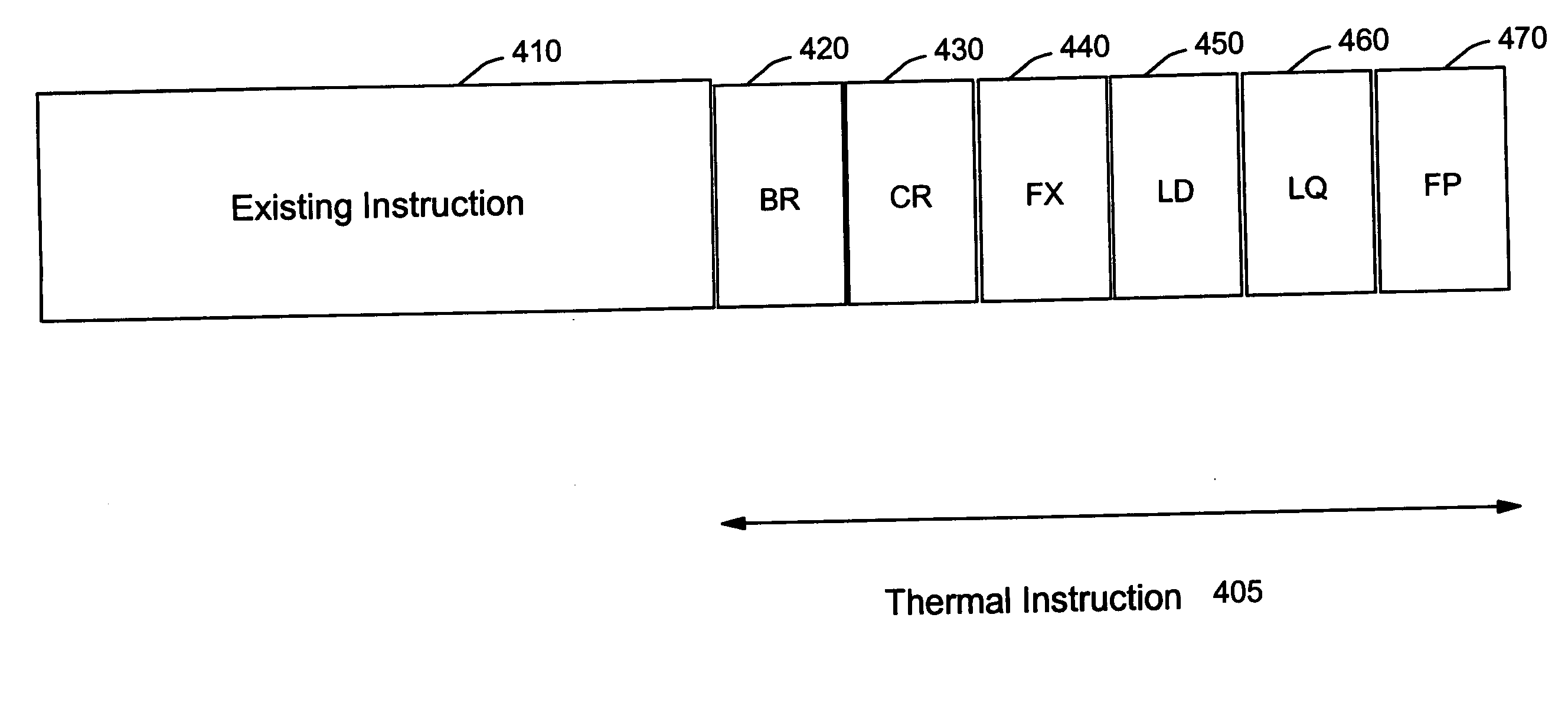
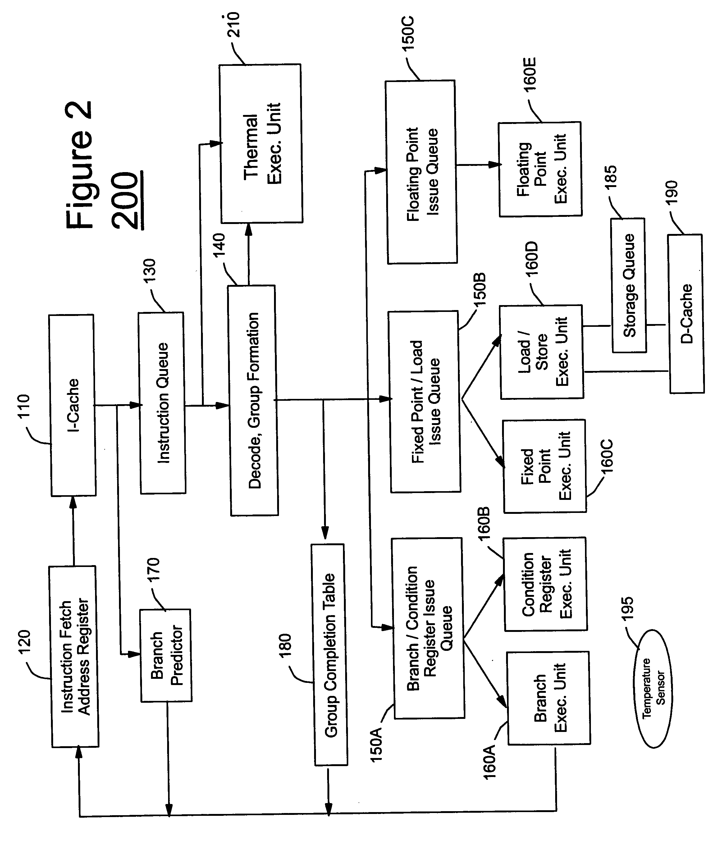
The present invention provides a method and structure for sensing temperature in a microprocessor without necessarily using a temperature diode sensor. The invention uses a thermal instruction appended to an instruction to be processed to determine the heat load associated with the instruction. The invention can measure the heat generation in real-time, at multiple locations on the chip, and can determine the amount of heat generated by each instruction. The invention can also scale with device lithography and avoids the problem of sensor placement. The invention can look, in advance, at the current instruction and can tell how much heat will be generated by the processing of the instruction. The invention provides a means of managing heat and avoiding heat building up at hot spots on the chip.

Problems solved by technology

The current state of the art is measurement resolution to within+ / −1 deg C. Internal diodes have to compromise with digital circuits and have much worse specifications.
It is challenging to integrate all of these analog components with noisy, high-speed digital circuits to measure temperatures accurately at many different locations.
Thus, instead of measuring the temperature of the device of interest, the diode sensor may be erroneously sensing the neighboring device.
However, such a LPF decreases the bandwidth to increase the response time of the sensors, thereby resulting in a lag time on the measurement.

Method used


Image

  • Instruction set with thermal opcode for high-performance microprocessor, microprocessor, and method therefor
  • Instruction set with thermal opcode for high-performance microprocessor, microprocessor, and method therefor
  • Instruction set with thermal opcode for high-performance microprocessor, microprocessor, and method therefor

Examples


Embodiment Construction

[0046] Referring now to the drawings, and more particularly to FIGS. 1-13, there are shown exemplary embodiments of the method and structures according to the present invention.

Exemplary Embodiment

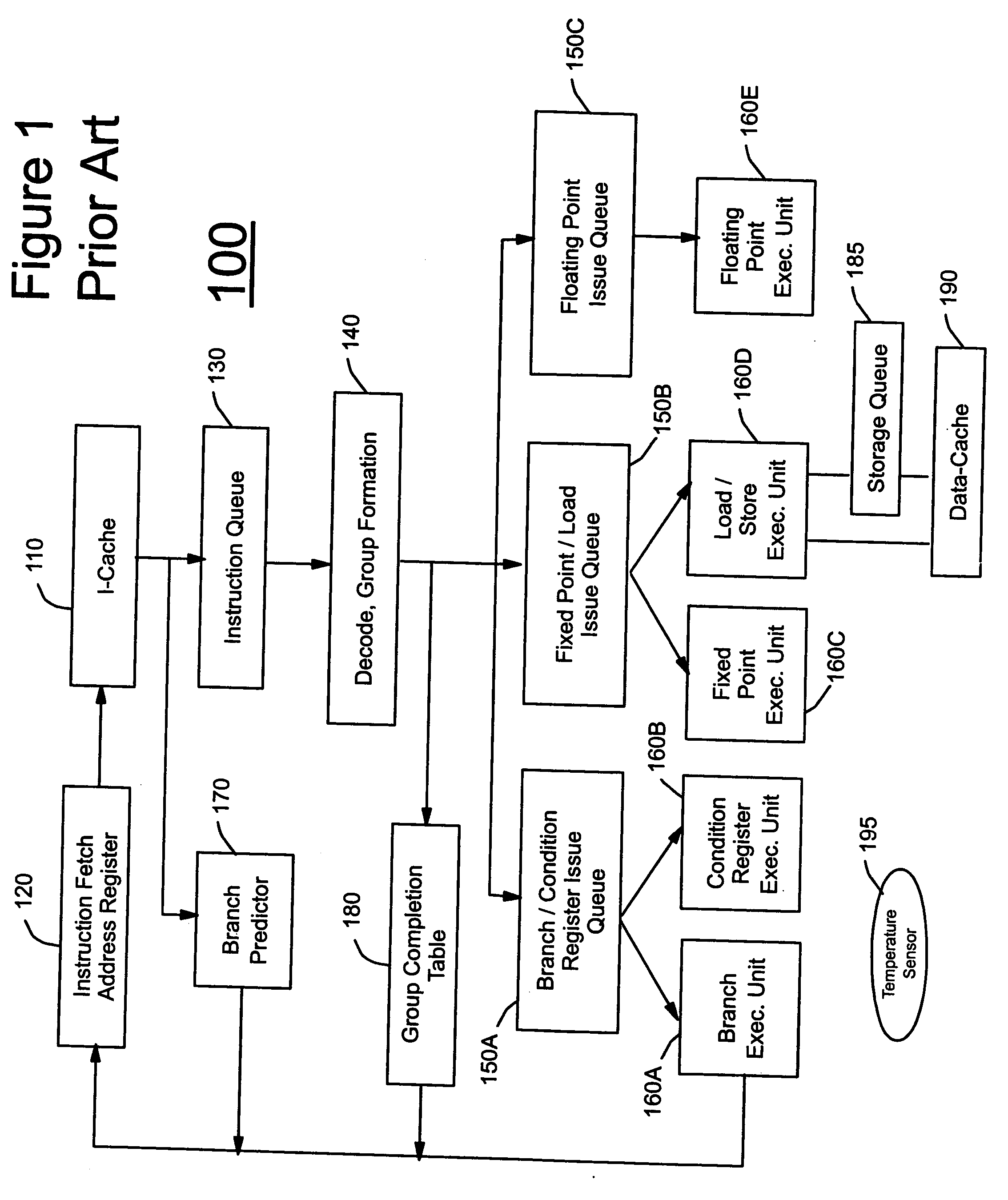
[0047]FIG. 1 shows the architecture of a conventional, exemplary current generation high-performance microprocessor 100, and more specifically a highly simplified block diagram of the IBM Power4® Microprocessor Core which is a speculative superscalar out-of-order execution design.

[0048] Instructions are loaded into the 64 KB I-cache 110, starting at the location indicated by the Instruction Fetch Address Register (IFAR) 120. A plurality (e.g., up to eight) of instructions are fetched per cycle into the instruction queue 130 and into the decoder 140 where they are grouped and sent to the appropriate Issue queues 150A (the branch / condition register issue queue), 150B (the fixed point / load issue queue), 150C (the floating point issue queue) and the corresponding Execution units (EU) 160A (...


PUM


Abstract

A method (and system) of managing heat in an electrical circuit, includes using a thermal instruction appended to an instruction to be processed to determine a heat load associated with the instruction.

Description

CROSS-REFERENCE TO RELATED APPLICATIONS [0001] The present application is related to U.S. patent application Ser. No. 10 / 892,211, filed on Jul. 16, 2004, to Sri Sri-Jayantha et al., entitled “METHOD AND SYSTEM FOR REAL-TIME ESTIMATION AND PREDICTION OF THE THERMAL STATE OF A MICROPROCESSOR UNIT”, having IBM Docket No. YOR920040069US1, assigned to the present Assignee and incorporated herein by reference.BACKGROUND OF THE INVENTION [0002] 1. Field of the Invention [0003] The present invention generally relates to a microprocessor and method therefor, and more particularly to an instruction set with thermal opcode for a high-performance microprocessor and a method therefor. [0004] 2. Description of the Related Art [0005] The current generation of 64-bit high-performance microprocessors such as the IBM Power4® have 174 million transistors interconnected with seven layers of copper metallurgy. It is fabricated in 0.18-μm complementary metal oxide semiconductor (CMOS) silicon-on-insulato...

Claims


Application Information

Patent Timeline
Patent Type & Authority Applications(United States)
IPC IPC(8): G06F1/30
CPCG06F1/206G06F9/30083G06F9/30145Y02B60/1275G06F9/30181G06F9/383G06F9/3885G06F9/30167Y02D10/00
Inventor DANG, HIEN P.SHARMA, ARUNSRI-JAYANTHA, SRI M.
Owner IBM CORP
Learn More