Implant that can be implanted in osseous tissue and method for producing said implant corresponding implant

a technology of implanted implants and bone tissue, applied in the field of medical technology, can solve the problems of preventing the successful integration of implants in bone tissue, affecting the stability of implants, and affecting the stability of implants, and achieves the effect of strong long-term anchoring of implants

Active Publication Date: 2006-05-18
WOODWELDING
View PDF65 Cites 209 Cited by
  • Summary
  • Abstract
  • Description
  • Claims
  • Application Information

AI Technical Summary

Benefits of technology

[0041] The use of a non-resorbable liquefiable material enables a strong long-term anchoring of th

Problems solved by technology

Implantation of such a dental implant is generally not possible until the cavity resulting from the extraction of the natural root to be substituted has filled with regenerated bone tissue, i.e. until after a waiting period of 3 to 6 months following the extraction.
Usually the screwed implant is not loaded immediately after implantation, as the risk is too high that the stress would cause the implant to move too much in relation to the bone tissue.
This would prevent a successful integration of the implant in the bone tissue (osseointegration).
It is well known that bone tissue tends to recede in an undesirable manner during the waiting periods mentioned above, in which the dental implant or jawbone is locally not loaded.
This has a negative effect on osseointegration during the second waiting period such that a kind of connective tissue forms in the gap between the alveolar wall and the implant, which connective tissue prevents osseointegration at least locally and is not able to lend the implant sufficient stability.
Thus the implant is no longer stabilized by ‘press-fit’ but sits loosely in the alveolus once more, so that conditions for osseointegration are not optimal in spite of the improved primary stability immediately after the implantation.
It is also evident that even after the osseointegration phase (second waiting period) these implants tend to loose their grip in the jawbone when loaded.
Although the surface geometries can raise the tension very loc

Method used


Image

  • Implant that can be implanted in osseous tissue and method for producing said implant corresponding implant
  • Implant that can be implanted in osseous tissue and method for producing said implant corresponding implant
  • Implant that can be implanted in osseous tissue and method for producing said implant corresponding implant

Examples


Embodiment Construction

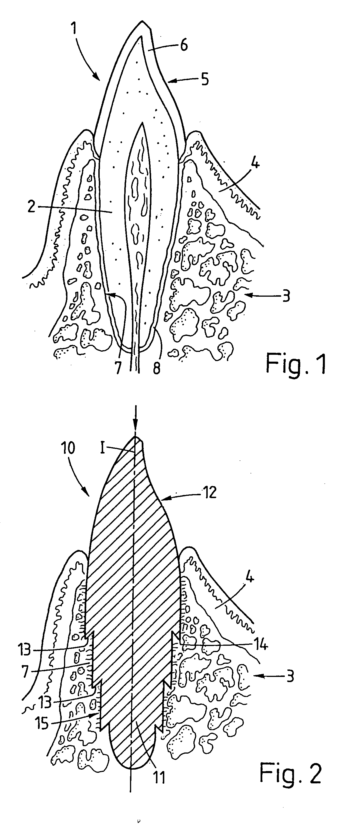
[0063]FIG. 1 shows in section across the jaw ridge a natural tooth 1, whose root 2 is ingrown in a jawbone 3. The jawbone 3 is covered by gums 4 (connective tissue and skin). The crown 5 protrudes from the jawbone and gums 4 and is coated with a layer of dental enamel 6, while the interior of the crown 5 and the root 2 consist of dentine. The root 2 is located in an alveolus (tooth socket) in the jawbone, wherein the bone tissue of the alveolus wall 7 (alveolar bone), compared with bone tissue further removed from the root 2, usually has a greater density and therefore a superior mechanical stability. Between the alveolus wall 7 and the root 2 lies the tooth membrane 8 containing collagen fibres by which the root 2 is attached to the alveolus wall 7. The fibres carry the tooth and couple forces acting on the tooth laterally into the bone tissue. On extraction of the tooth, the tooth membrane is destroyed. It does not regenerate.

[0064]FIG. 2 shows, in section similar to FIG. 1, an i...


PUM


Abstract

A bone implant (10) is implanted in a cavity parallel to an implant axis (I) and without substantial rotation. The implant includes, on an implant portion to be implanted, cutting edges (14), which do not extend in a common plane with the implant axis and are facing toward the distal end of the implant. The implant also includes surface ranges (16) of a material that is liquefiable by mechanical oscillations. The cutting edges (14) are dimensioned such that they are lodged in the cavity wall after implantation. For implantation, the implant is impinged with mechanical oscillations, resulting in the thermoplastic material being at least partially liquefied and pressed into unevennesses and pores of the cavity wall to form a form-fit and/or material-fit connection between implant (10) and cavity wall, when re-solidified. The cutting edges (14) anchor the implant in the cavity wall.

Description

BACKGROUND OF THE INVENTION [0001] 1. Field of the Invention [0002] The invention lies in the field of medical technology and concerns an implant to be implanted in bone tissue, which implant may be a standardized one being implanted in a cavity especially created or adjusted for the purpose, or an individual implant being implanted in an individual bone cavity (e.g. dental implant, joint implant, or an implant to fill a bone defect). The invention further concerns methods for producing and implanting the implant. [0003] 2. Description of Related Art [0004] Implants to be implanted in bone tissue are usually implanted in bone cavities, which are especially created for the purpose (e.g. bore or stepped bore) or which are caused by other circumstances, e.g. trauma or degenerative disease. According to state-of-the-art technology, such implants are either fitted into the cavity by means of cement placed around the implant, or the shape of the implant is adapted to the cavity so accurat...

Claims


Application Information

Patent Timeline
IPC IPC(8): A61C8/00A61B17/68A61B17/86A61B17/88A61C13/00A61F2/00A61F2/30
CPCA61B17/68A61B2017/00955A61C8/0012A61C8/0016A61C8/0018A61F2210/0071A61C8/0089A61C13/0004A61F2002/30065A61F2002/4683A61C8/0045A61B17/86A61F2/30A61F2/00A61C13/0003
Inventor MAYER, JORGAESCHLIMANN, MARCELTORRIANI, LAURENTRAST, CHRISTOPHERMULLER, ANDREA
Owner WOODWELDING
Why Eureka
Try Eureka