

Shape measuring apparatus
a technology of measuring apparatus and shape, which is applied in the direction of measuring devices, instruments, using optical means, etc., can solve the problems of increasing the extent of blurring of images, difficult to identify the true edge, and difficulty in irradiating objects with exactly parallel light beams, etc., to achieve good image, good image, and little blurring
- Summary
- Abstract
- Description
- Claims
- Application Information
AI Technical Summary
Benefits of technology
Problems solved by technology
Method used
Image

Examples
embodiment
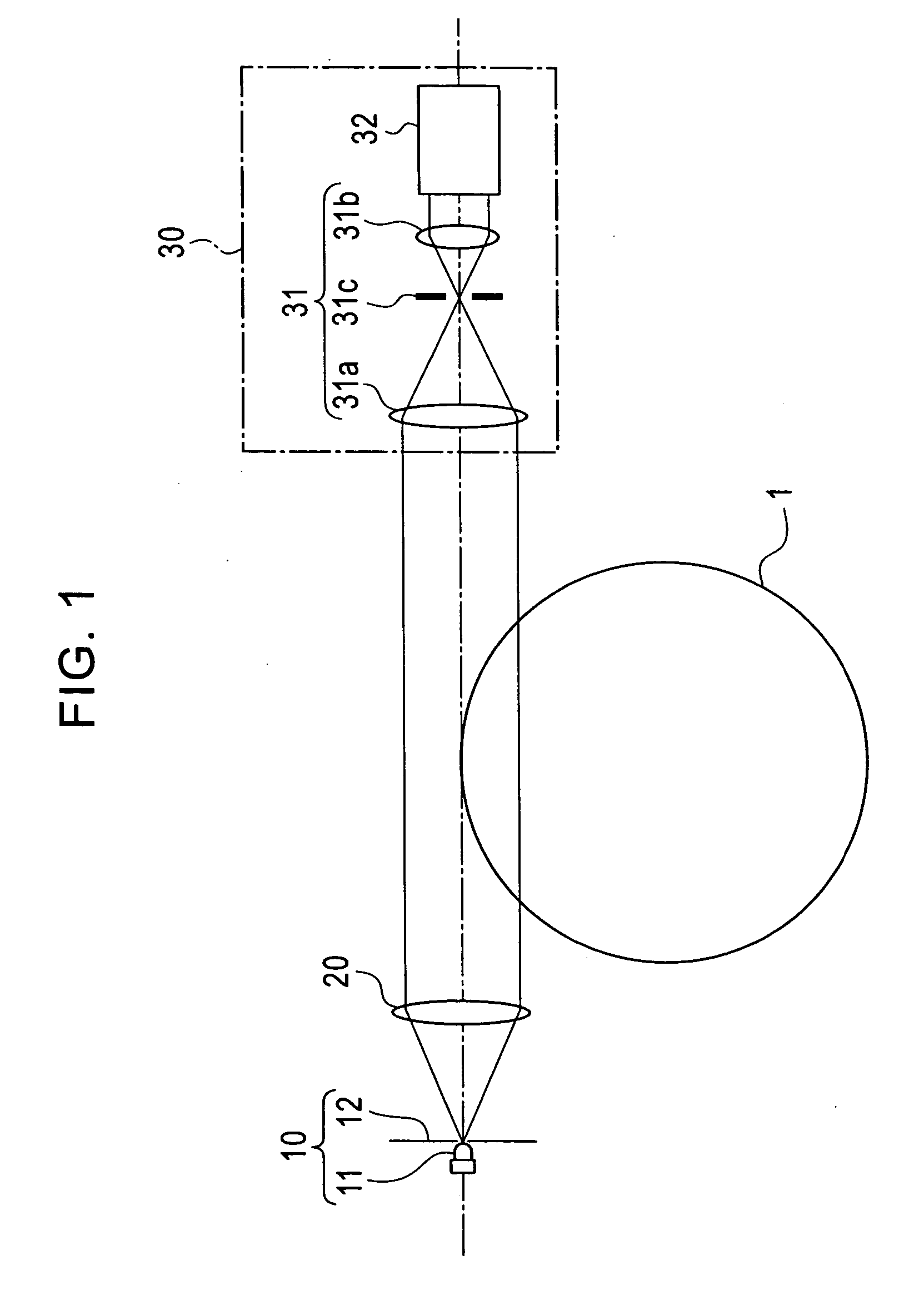
Refer to FIG. 1
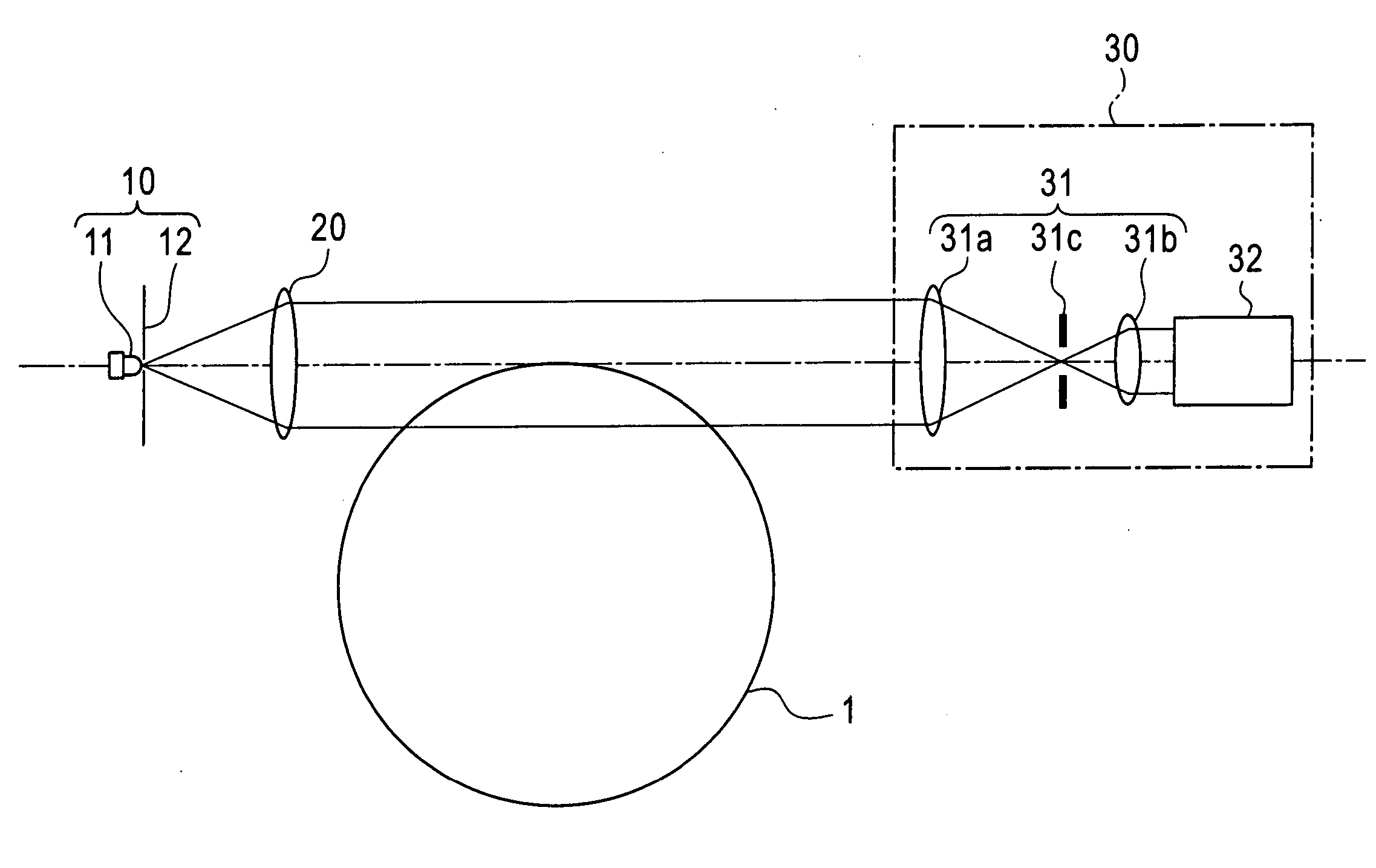
[0024] As shown in FIG. 1, the shape measuring apparatus according to the embodiment comprises a point light source 10, a collimator lens 20 used for parallel optics of the point light source 10, and image pickup optics 30. The point light source 10 has a white LED 11 and a pinhole 12 having an opening which has a size, for example, on the order of φ4100 μm to φ200 μm and which is positioned at focal points of the collimator lens 20. Light emitted from the white LED 11 and scattered from the openings impinges upon the collimator lens 20 for forming a parallel beam.
[0025] The image pickup optics 30 includes a telecentric lens device 31 and a two-dimensional CCD line sensor 32. Light traveling from the collimator lens 20 passes through the telecentric lens device 31 from a semiconductor wafer 1 serving as an object to be measured and impinges upon the two-dimensional CCD line sensor 32. An image of the semiconductor wafer 1 is projected by using the two-dimensional CCD...
examples
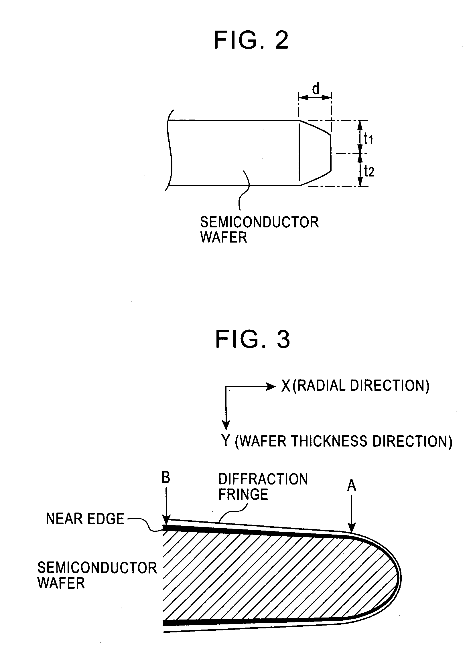
Refer to FIG. 3 to FIG. 6B
[0029] By using shape measuring apparatuses according to an example and a comparative example, an image of an external edge of a semiconductor wafer having a diameter and a thickness on the order of 300 mm and 0.8 mm, respectively, was set at a two-dimensional CCD line sensor in order to examine edge position information from the image.
[0030] In the structure of the shape measuring apparatus according to the example, the point light source used had a white LED (a surface emitting diode having a size of approximately 500 μm), and a pinhole including an opening having a size of φ200 μn. The white LED is one in which the surface of an InGaN blue LED is coated with, for example, YAG:Ce phosphor. This type of white LED produces white light using blue light of the LED and yellow light of the phosphor by exciting the phosphor (which emits yellow light) with the light of the blue LED. For parallel optics for the point light source, a collimator lens having a foca...
PUM
 Abstract
Description
Claims
Application Information