Optical pickup device

a pickup device and optical technology, applied in the field of optical pickup devices, can solve the problems of insufficient product value of optical disk players/recorders, inability to only properly perform recording and/or reproduction of information, and increase costs, so as to achieve the effect of reducing the risk of coma, and reducing the cost of light us

Inactive Publication Date: 2006-05-25
KONICA MINOLTA OPTO
View PDF4 Cites 2 Cited by
  • Summary
  • Abstract
  • Description
  • Claims
  • Application Information

AI Technical Summary

Benefits of technology

[0026] According to the above optical pickup device, the first objective optical system is dedicated to the first beam or shared by the first and second beams, and the second objective optical system is dedicated to the third beam or shared by the second and third beams. This can make the design more flexible than that in the case where a single optical system is shared by three kinds of beams, thus maintaining a compact struct...

Problems solved by technology

By the way, the capability of only properly performing recording and/or reproduction of information for such a type of high density optical disks is not enough for a product value of optical disk players/recorders.
However, this method requires three types of optical systems, which is disadvantageous for miniaturization and increases costs.
In performing recording and/or reproduction of information in a compatible manner for disks of three or more standards, however, the light use efficiency becomes low, that is, the spot light intensity becomes low recording and/or reproduction of disks of any one of the standards.
Specifically, when both the blue-violet laser beam and infrared laser beam are ensured to have the diffraction efficiencies, the diffraction angle ...

Method used


Image

  • Optical pickup device
  • Optical pickup device
  • Optical pickup device

Examples


example 1

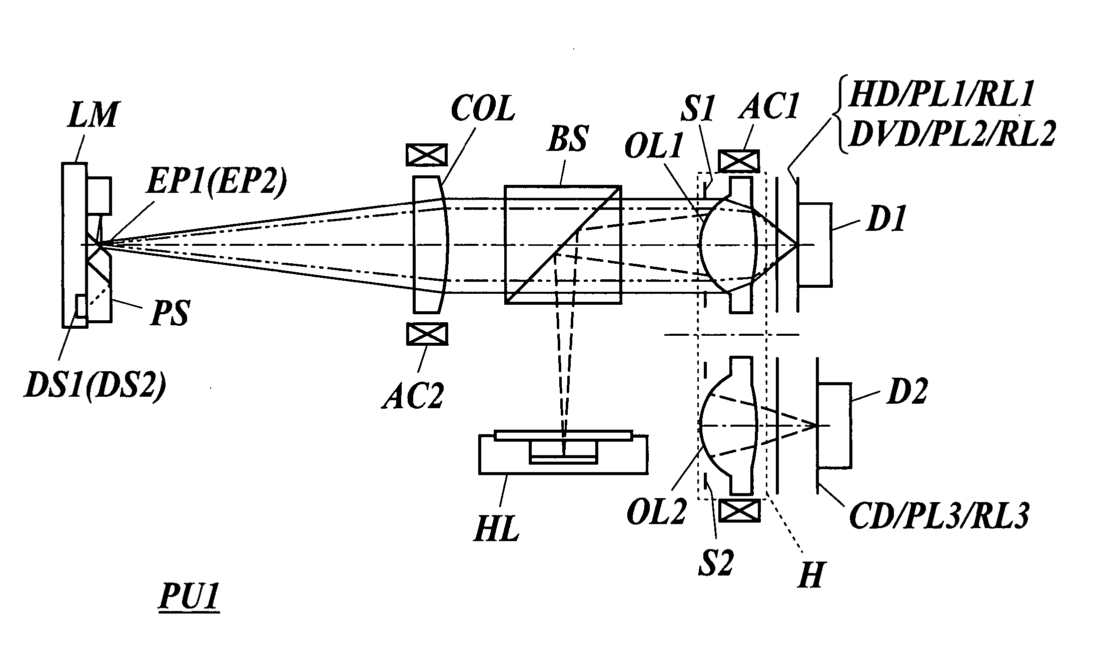
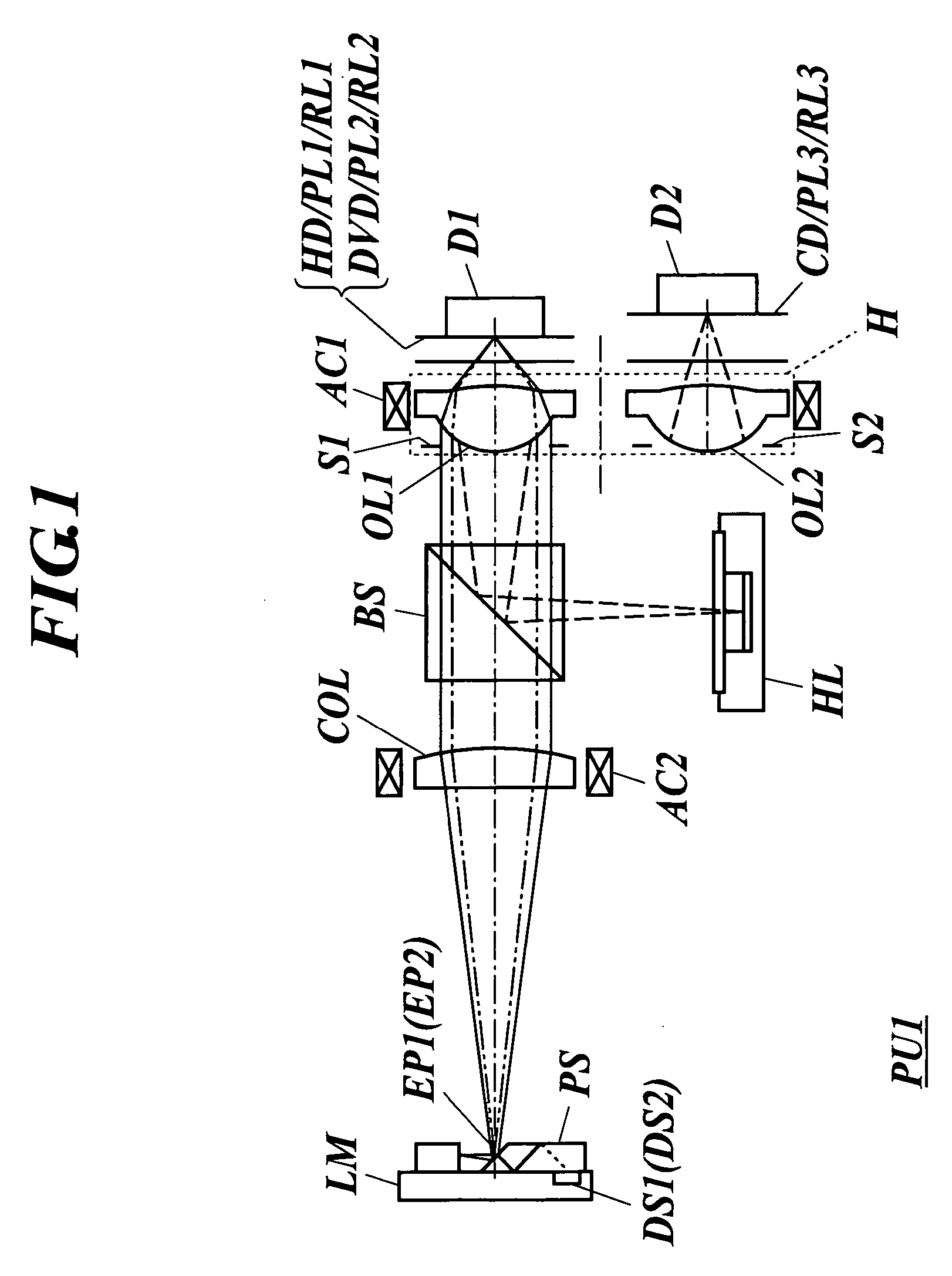
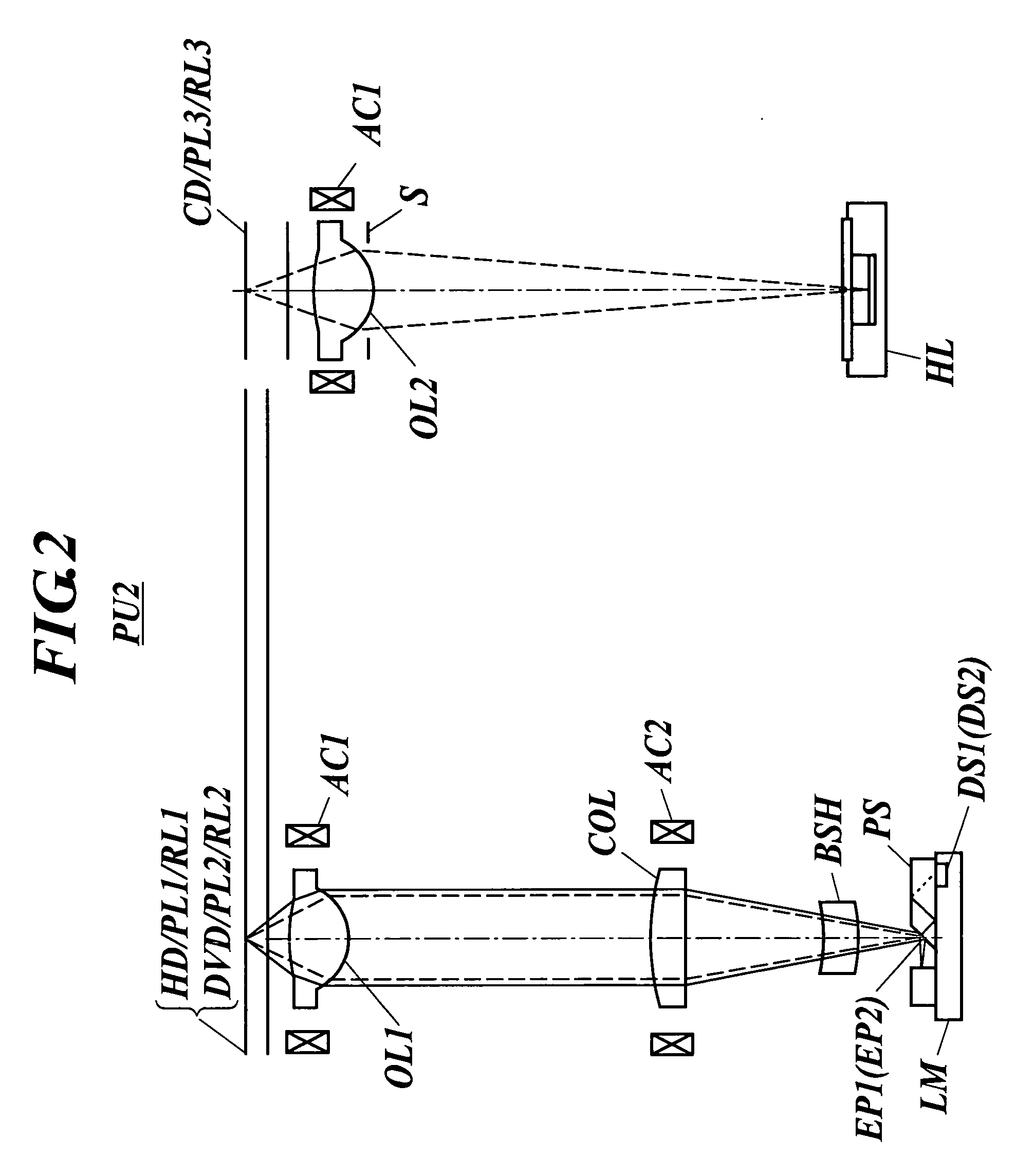
[0121] Next, a description is given of an example. Example 1 is an example of the first objective optical element OL1 suitable for the optical pickup device shown in FIGS. 1 to 3. The second objective optical element dedicated to the CD can be a publicly known optical element. Lens data of Example 1 is shown in Table 1. Hereinafter (including the lens data in the table), an exponential in decimal (for example, 2.5×10⁻³) is represented using E (for example, 2.5E-3).

TABLE 1Lens data of Example 1Objective Lensf1 = 2.30 mmf2 = 2.36 mmFocal LengthImage SideNA1: 0.65NA2: 0.65NumericalApertureSecond Surfacen1: 3n2: 2DiffractionOrderMagnificationm1: 0m2: 0i-thsur-dinidinifaceri(407 nm)(407 nm)(655 nm)(655 nm)0∞∞1∞0.010.01(Stop(φ2.99 mm)(φ 3.07 mm)Size)21.551961.400001.5598061.400001.5407253−8.239711.121.01.161.04∞0.61.618690.61.577525∞*di represents a distance between the i-th and (i + 1)-th surfaces.Aspheric dataSecond surfaceAspheric coefficientκ−2.5377E−01A4−9.5198E−03A6−5.2537E−03A84....


PUM


Abstract

An optical pickup device, including: first, second and third light sources performing recording and/or reproduction of information for information recording surfaces of first, second and third optical information recording medium each having a protective substrate with a thickness t1, t2 and t3, respectively; a first objective optical system for guiding at least the first beam to the information recording surface of first optical information recording medium; second objective optical system provided separately from the first objective optical system, for guiding at least the third beam to information recording surface of the third optical information recording medium; and at least one light receiving element for detecting light reflected on the information recording surfaces of the first to third optical information recording media.

Description

TECHNICAL FIELD [0001] The present invention relates to an optical pickup device capable of performing recording and / or reproduction of information in a compatible manner for different kinds of optical information recording media (also called optical disks). TECHNICAL BACKGROUND [0002] In recent years, in optical pickup devices, laser sources used as light sources for reproducing information recorded on optical disks or recording information on optical disks have increasingly shorter wavelength. For example, laser sources with wavelengths of 400 to 420 nm, such as a blue-violet semiconductor laser and a blue SHG laser in which wavelength of an infrared semiconductor laser is converted using a second harmonic, have been put into practical use. Using these blue-violet laser sources, it is possible to, in the case of using an objective lens with a numerical aperture (NA) same as that of DVDs (digital versatile disks), record 15 to 20 GB of information on an optical disk with a diameter...

Claims


Application Information

Patent Timeline
IPC IPC(8): G11B7/00
CPCG11B7/127G11B7/1376G11B7/1395G11B2007/0006
Inventor ATARASHI, YUICHIWACHI, MIKAHASHIMURA, JUNJI
Owner KONICA MINOLTA OPTO
Why Eureka
Try Eureka