Operation control of fuel cell system

a fuel cell and operation control technology, applied in the direction of cell components, cell component details, electrochemical generators, etc., can solve the problems of significant troubles, interference with the stable output of electric power, and misjudgment of the abnormal state of the fuel cell system, so as to reduce the potential effect of varying decompression performance and reduce the pressure of hydrogen supply

Inactive Publication Date: 2006-05-25
TOYOTA JIDOSHA KK
View PDF3 Cites 28 Cited by
  • Summary
  • Abstract
  • Description
  • Claims
  • Application Information

AI Technical Summary

Benefits of technology

[0009] In order to attain at least part of the above and the other related objects, the present invention is directed to a fuel cell system including: a fuel cell stack that receives supplies of hydrogen and oxygen and generates electric power by an electrochemical reaction of the hydrogen and oxygen supplies; a hydrogen tank that stores hydrogen under a pressure of not lower than the atmospheric pressure, before the supply to the fuel cell stack; a hydrogen supply conduit that connects the hydrogen tank to the fuel cell stack; a pressure regulator that is provided in the pathway of the

Problems solved by technology

The varying pressure of the hydrogen supply may interfere with stable output of electric power.
Even in the normal operation state of the fuel cell system, the varying pressure of the hydrogen supply may activate a safety device and le

Method used


Image

  • Operation control of fuel cell system
  • Operation control of fuel cell system
  • Operation control of fuel cell system

Examples


Embodiment Construction

[0033] One mode of carrying out the invention is described below as a preferred embodiment in the following sequence: [0034] A. General Configuration of Fuel Cell System [0035] B. Control in Fuel Cell System [0036] C. Operation Principle of Pressure Regulator [0037] D. Atmospheric Pressure-Based Correction Process [0038] E. Estimation Method of Nitrogen Concentration

[0039] A. General Configuration of Fuel Cell System

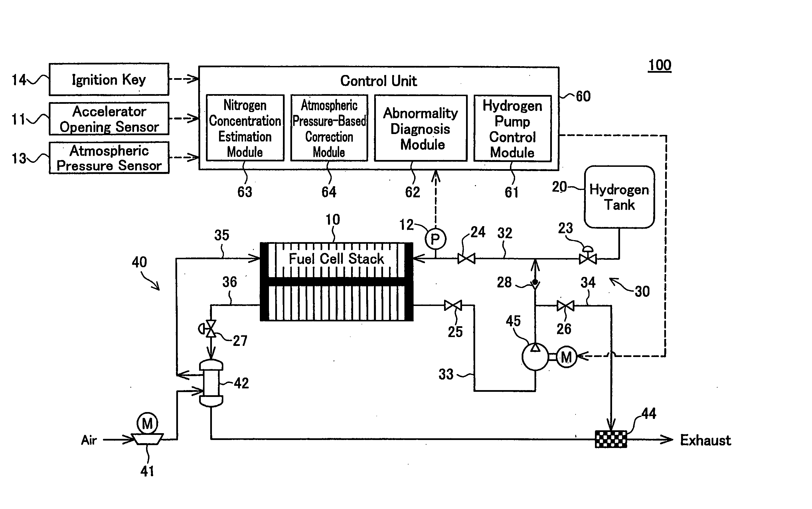
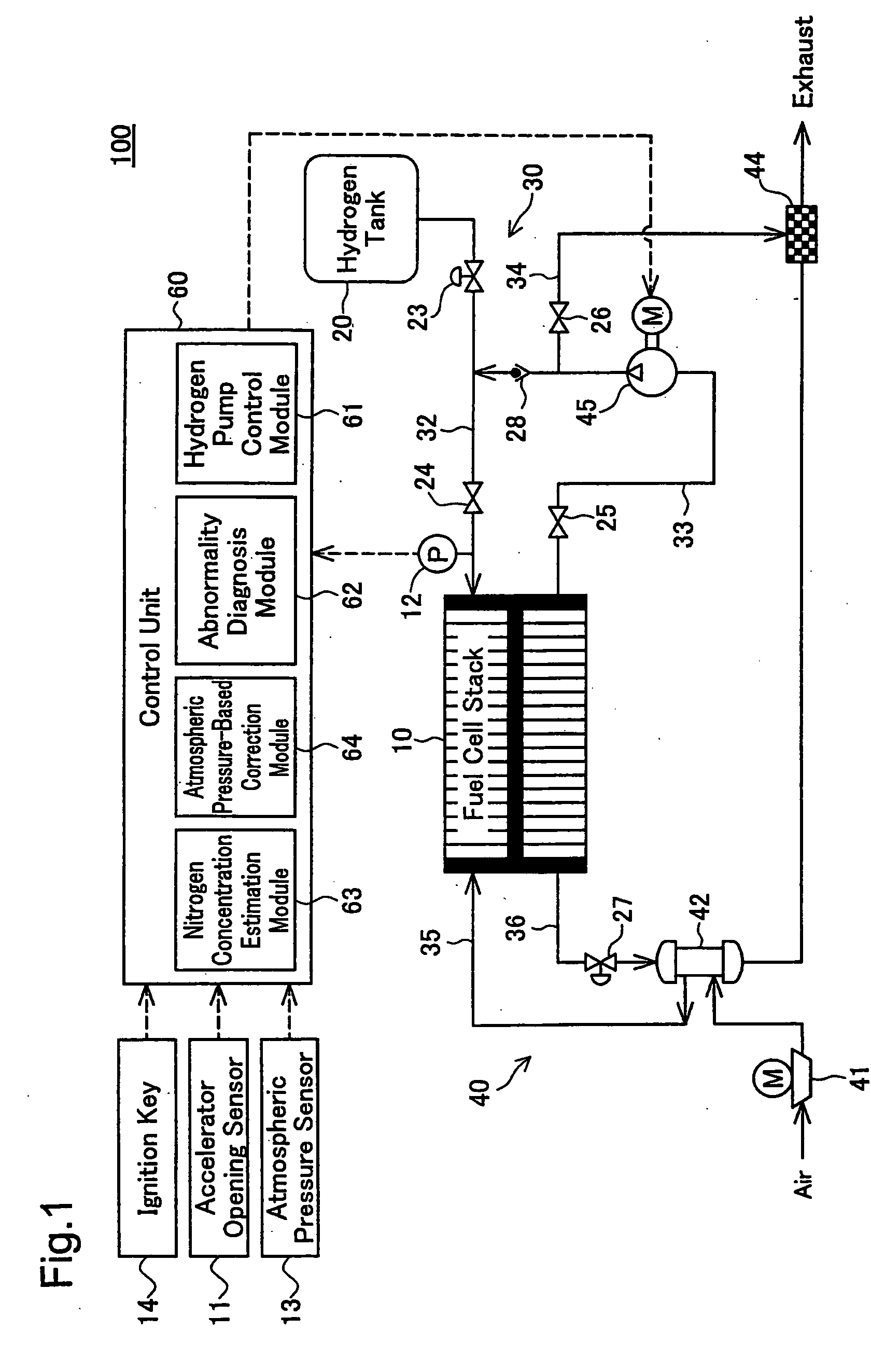
[0040]FIG. 1 schematically illustrates the configuration of a fuel cell system 100 in one embodiment of the invention. The fuel cell system 100 of the embodiment is mounted as a power source on an electric vehicle driven with a motor. When the driver turns an ignition key 14 on and depresses an accelerator, the fuel cell system 100 starts power generation according to the driver's depression amount of the accelerator measured by an accelerator opening sensor 11 and enables the electric vehicle to run with the generated electric power. The fuel cell system 100 is mounte...


PUM


Abstract

In a fuel cell system of the invention, a pressure regulator is provided in the pathway of a hydrogen supply conduit that connects a hydrogen tank to a fuel cell stack. An anode off gas discharged from the fuel cell stack is recirculated through a recirculation pipe into the hydrogen supply conduit. A hydrogen pump is provided in the pathway of the recirculation pipe to increase the pressure of the anode off gas. A control unit of the fuel cell system includes a hydrogen pump control module, an abnormality diagnosis module, and an atmospheric pressure-based correction module. The hydrogen pump control module regulates the rotation speed of the hydrogen pump corresponding to a power demand to be output from the fuel cell system. The abnormality diagnosis module detects an abnormal state, based on a result of determination of whether the pressure of the hydrogen supply measured by a pressure sensor is within a certain range defined by two preset threshold values. The atmospheric pressure-based correction module corrects the rotation speed of the hydrogen pump and the threshold values used for abnormality diagnosis according to the atmospheric pressure measured by an atmospheric pressure sensor. Even in the state of unstable output of the pressure regulator with a variation of the atmospheric pressure, such correction compensates for the varying flow rate of the hydrogen supply to the fuel cell stack and thus effectively prevents misjudgment of abnormality diagnosis. Namely the technique of the invention reduces the potential effect of the varying pressure of the hydrogen supply to the fuel cell system with a variation of the atmospheric pressure.

Description

[0001] This is a Continuation of International Application No. PCT / JP2004 / 006361 filed Apr. 30, 2004, which claims the benefit of Japanese Patent Application No. 2003-135463 filed May 14, 2003. The entire disclosure of the prior applications is hereby incorporated by reference herein in its entirety.BACKGROUND OF THE INVENTION [0002] 1. Field of the Invention [0003] The present invention relates to a technique of controlling operations of a fuel cell system. [0004] 2. Description of the Related Art [0005] Fuel cell systems generating electric power by an electrochemical reaction of hydrogen with oxygen have recently drawn attention as the novel energy source. The fuel cell system requires a supply of hydrogen for power generation. The hydrogen to be supplied to the fuel cell system is stored under pressure in a hydrogen tank and is depressurized to a preset pressure level by a pressure regulator, prior to the supply. [0006] A typical example of the pressure regulator to depressurize...

Claims


Application Information

Patent Timeline
IPC IPC(8): H01M8/04H01M8/00H01M8/06H01M8/10
CPCH01M8/04097H01M8/04223H01M8/0662Y02E60/50H01M8/241H01M8/2457H01M8/2483
Inventor YOSHIDA, NAOHIROBONO, TETSUYAKURITA, KENJIMORI, HIROAKI
Owner TOYOTA JIDOSHA KK
Why Eureka
Try Eureka