Method for detecting/adjusting synchronous motor rotor position
a technology of synchronous motor and rotor position, which is applied in the direction of motor/generator/converter stopper, electronic commutator, dynamo-electric converter control, etc., can solve the problems of expensive apparatus adopting this method, and achieve the effects of improving the positioning accuracy of the rotational position detector, good performance and excellent productivity
- Summary
- Abstract
- Description
- Claims
- Application Information
AI Technical Summary
Benefits of technology
Problems solved by technology
Method used
Image
Examples
embodiment 1
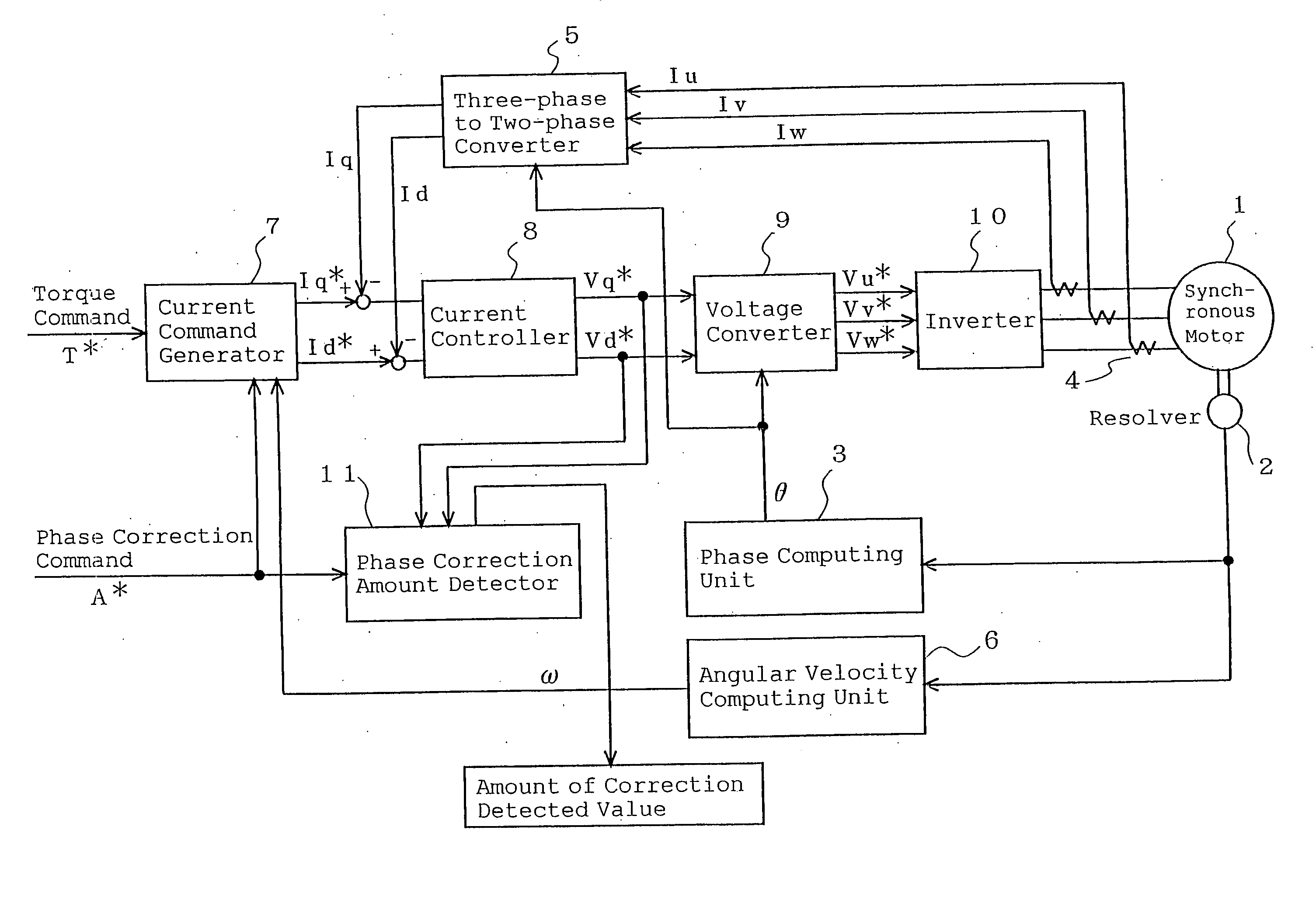
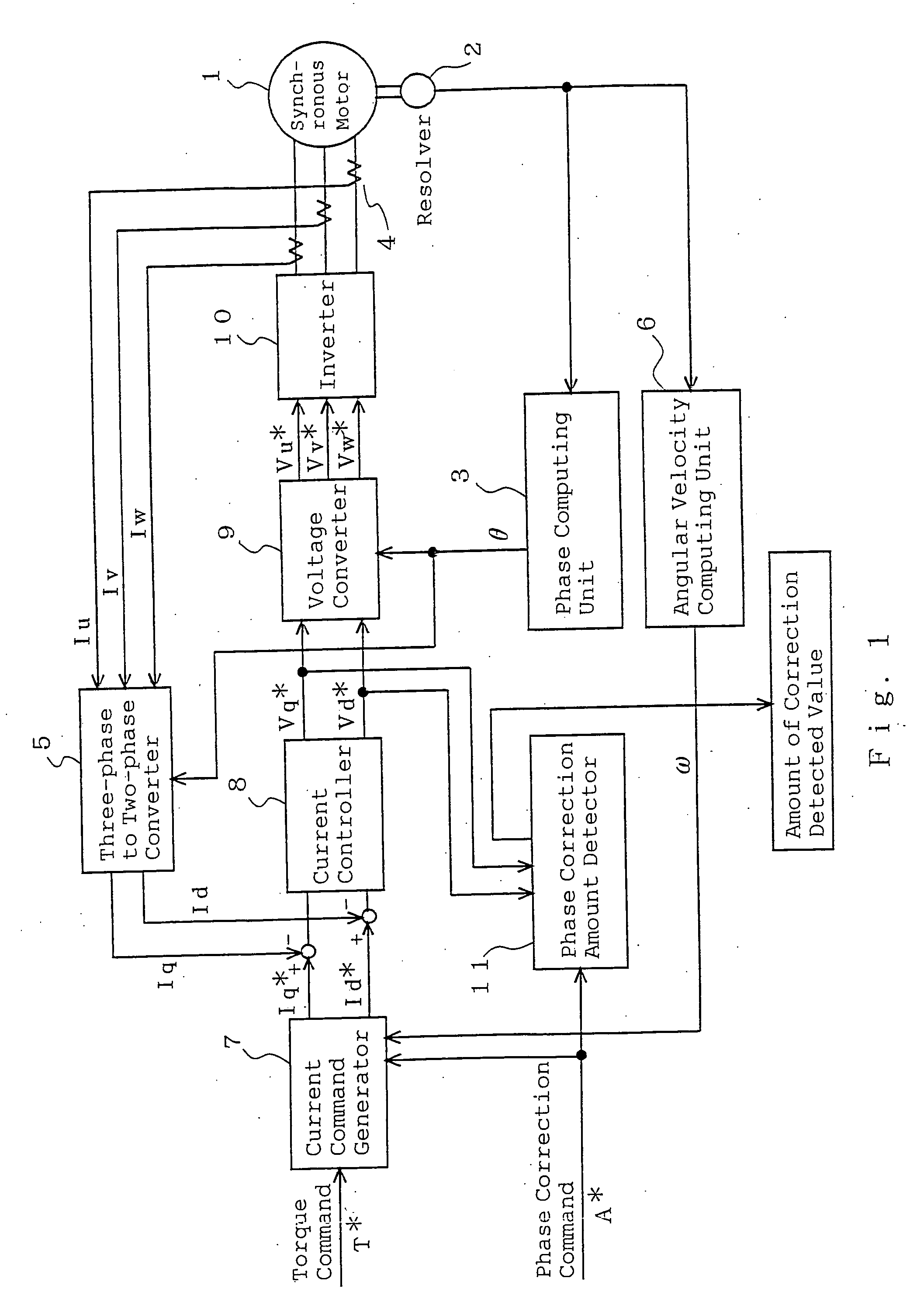
[0014]FIG. 1 is a block diagram of a motor apparatus for explaining an adjustment method of rotor position detection of a synchronous motor of Embodiment 1 according to the present invention. A synchronous motor apparatus includes a synchronous motor 1 having a permanent magnet field or winding field and a controller for controlling the synchronous motor 1. The controller includes a resolver 2, which is a rotational position detector, for detecting a rotor position of the synchronous motor 1; a phase computing unit 3 for computing a rotor position angle θ from an output of the resolver 2; a current detector 4 for detecting three-phase currents Iu, Iv, and Iw of the synchronous motor 1; and a three-phase to two-phase converter 5 for converting the rotor position angle θ and the three-phase currents Iu, Iv, and Iw to d-axis and q-axis currents (actual current).
[0015] Further, the controller includes an angular velocity computing unit 6 for determining the rotational angular velocity ...
embodiment 2
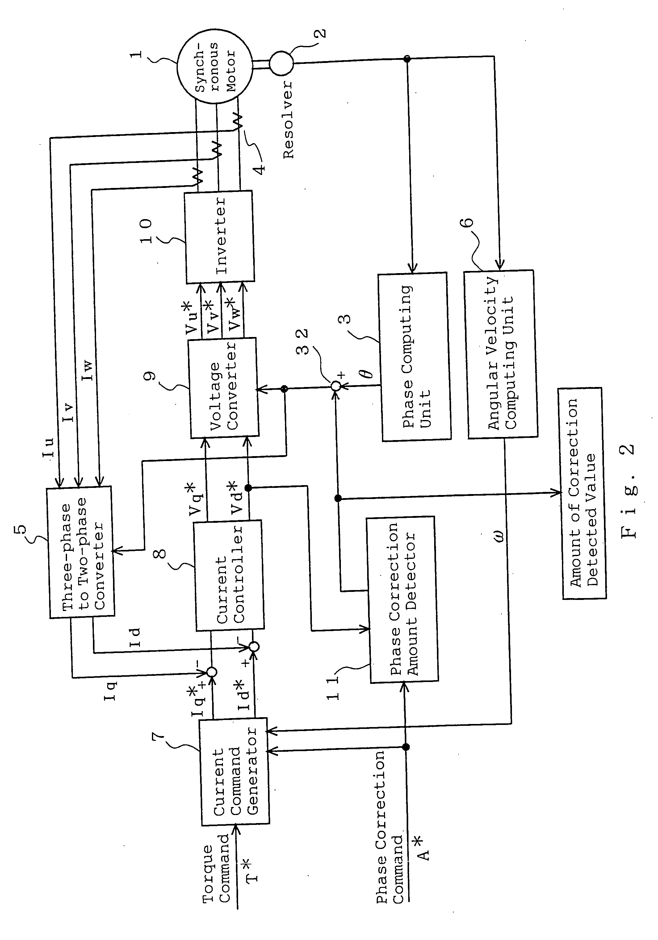
[0029]FIG. 2 is a block diagram for explaining an adjustment method of rotor position detection of a synchronous motor of Embodiment 2 according to the present invention. Referring to the drawings, the same reference numerals as those shown in FIG. 1 of Embodiment 1 represent the same or corresponding elements and elements different from FIG. 1 will be mainly described. A phase correction amount detector 11 inputs a d-axis voltage command Vd* to determine an amount of offset Δθ concerning a rotor position angle θ and outputs it to an adder 32 and also outputs it as an amount of correction detected value. The adder 32 adds the amount of offset Δθ to the rotor position angle θ of a phase computing unit 3.
[0030] A method of determining the amount of offset Δθ will be described. In Embodiment 1, the phase correction command for commanding adjustment for a rotational position deviation makes the d-axis current command and the q-axis current command zero regardless of the torque command ...
embodiment 3
[0036] Next, an adjustment method of mechanically shifting the position of a rotational position detector in a rotation direction will be described specifically. FIG. 3 is a longitudinal sectional view showing a synchronous motor of Embodiment 3 and FIG. 4 is a front view thereof. In the figures, a synchronous motor is composed of a rotor 12 wound by a field winding 12a, a stator 13 wound by three-phase stator windings 13a, a front bracket 14 and a rear bracket 15 holding the rotor 12 and the stator 13, a rotational position detector 16 for detecting a rotational state of the rotor 12, and the like. The rotor 12 is of a claw pole type.
[0037] The rotor 12 includes a rotational shaft 19 rotatably supported by the front bracket 14 and the rear bracket 15 via bearings 17 and 18 on both sides. One end portion of the rotational shaft 19 protrudes from the front bracket 14 and a pulley 20 is fixed on its end portion. Further, two slip rings 21 are assembled on the other end portion of the...
PUM
 Abstract
Description
Claims
Application Information
 - R&D
- Intellectual Property
- Life Sciences
- Materials
- Tech Scout
- Unparalleled Data Quality
- Higher Quality Content
- 60% Fewer Hallucinations
Browse by: Latest US Patents, China's latest patents, Technical Efficacy Thesaurus, Application Domain, Technology Topic, Popular Technical Reports.
© 2025 PatSnap. All rights reserved.Legal|Privacy policy|Modern Slavery Act Transparency Statement|Sitemap|About US| Contact US: help@patsnap.com


