Optical recording and reading equipment

a technology of optical applied in the field of data recording and reading equipment, can solve the problems of limited optical efficiency, increased manufacturing cost, complicated system design, etc., and achieve the effect of reducing laser noise, reducing laser noise, and large laser nois

Inactive Publication Date: 2006-06-01
HITACHI LTD
View PDF5 Cites 7 Cited by
  • Summary
  • Abstract
  • Description
  • Claims
  • Application Information

AI Technical Summary

Benefits of technology

[0017] In this case, modulation is made by the laser beam itself on the subject optical disk. A DC voltage is applied to the modulator to change the voltage between reading and writing. The response time at a power change from reading to writing in the modulator is also improved up to 40 Gb/s (response time: 15 PS, pico: 10−12) (see FIG. 8). And, because the modulator response time is lower enough than the rotation speed of the present optical disks that is limited at 10,000 rpm (revolutions per minutes (cycle: about 6 milliseconds, milli: 10−3), the modulator design can

Problems solved by technology

And, this comes to cause the system design to be complicated and the manufacturing cost to increase.
The output beam power at the root of the LD goes down to 2 mW or under when in reading from an optical disk due to the beam output from the surface of the disk and the limited efficiency of the optical pick-up for using the beam.
When in reading and erasing, the laser beam output becomes larger than that when

Method used


Image

  • Optical recording and reading equipment
  • Optical recording and reading equipment
  • Optical recording and reading equipment

Examples


first embodiment

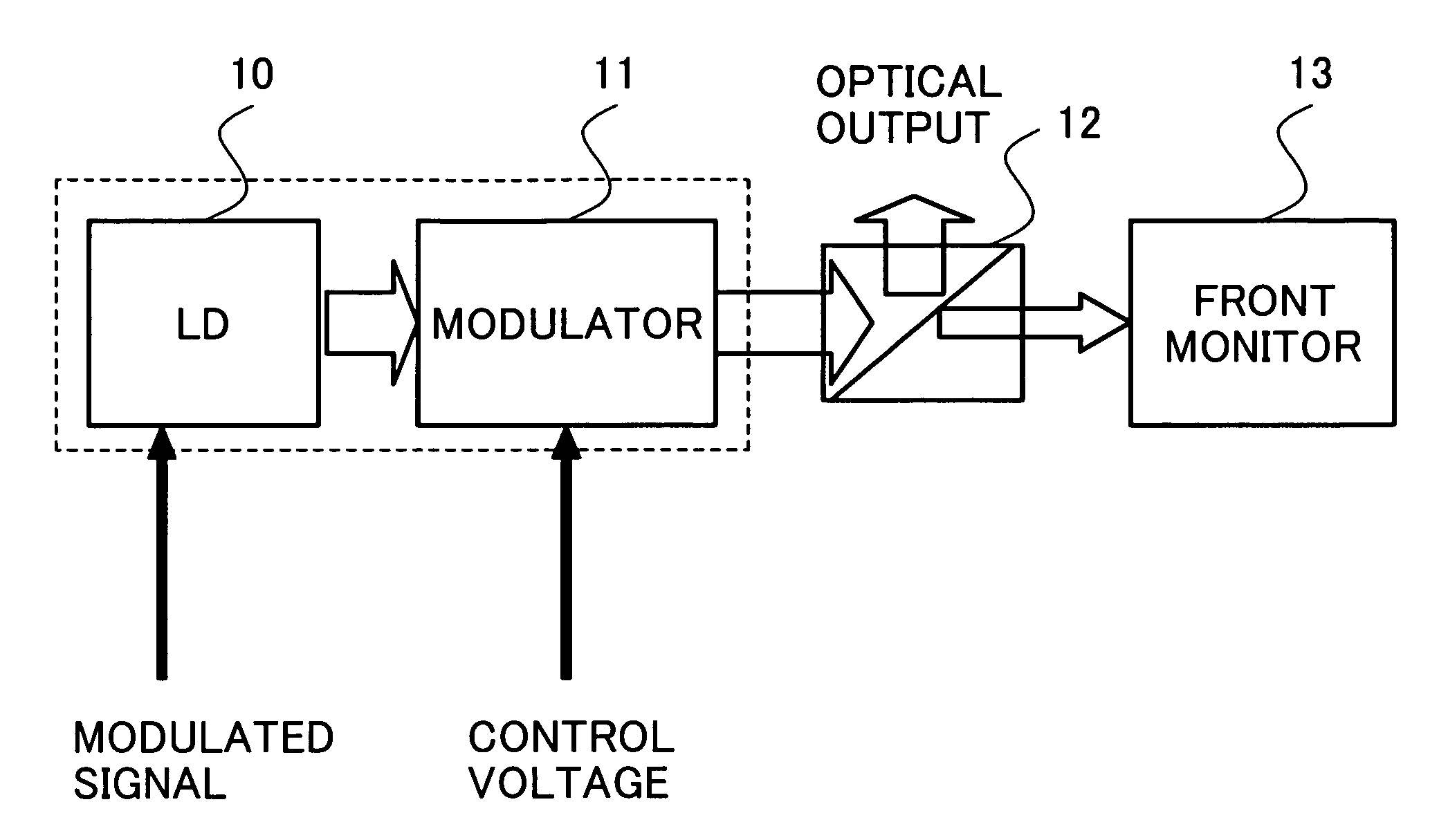
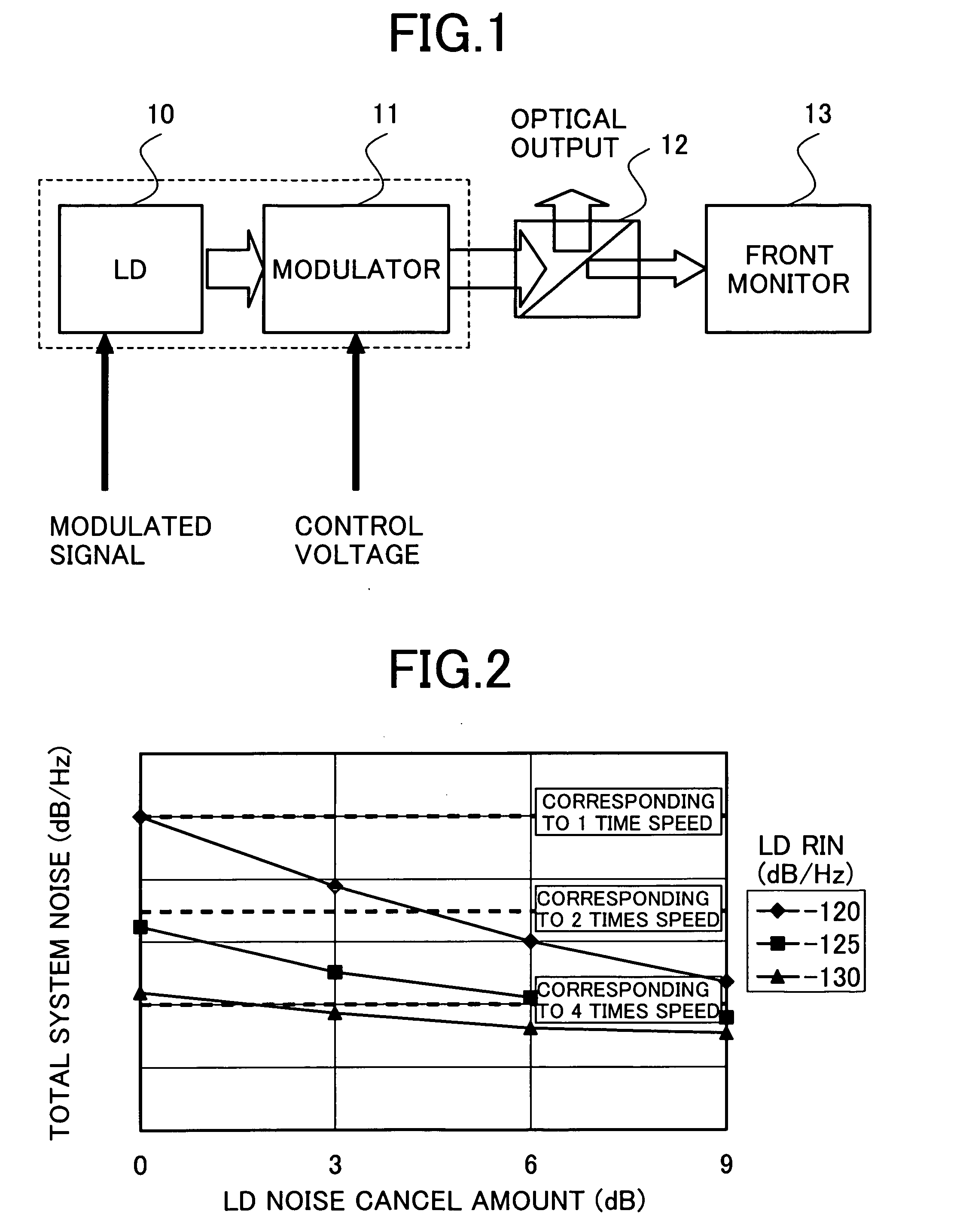
[0037] At first, a description will be made for an optical disk system that uses a laser disposed so as to precede a modulator in the first embodiment with reference to FIG. 1. The value of the noise level (RIN) is lowered up to a level required by the system when in reading. At that time, a laser output power with which the required RIN value is reached is set and the attenuation value of the modulator disposed preceding the laser is controlled with a voltage so that the attenuation reaches the specified 0.35 mW on the surface of the subject disk. In the BD standard, correspondence to two-layer disks is also ruled. The reading power of the 2-layer disks is set at 0.7 mW. More concretely, in this semiconductor laser element, the beam output from the beam source is inputted to the modulator 11 disposed adjacently. When in recording and erasing, no voltage is applied to the modulator 11 so that the beam passes through the modulator 11 as much as possible.

[0038] When in reading, a vol...

second embodiment

[0039]FIG. 9 shows the second embodiment. Basically, the same items as those in the first embodiment will be omitted here. In this second embodiment, a semiconductor chip in which a modulator and an LD are integrated is used. This is only a difference from the first embodiment. In case an electro absorption type modulator is used, the laser can also be integrated in the semiconductor chip as to be described below. This integration is effective to reduce the semiconductor chip in size significantly. Slim-sized disk drives have been required to be developed for optical disks of PCs, particularly for lap-top PCs. Those compact-sized disk drives will thus come to be reduced in size more and more indispensably to enable compatibility among CD, DVD, and BD. In case the modulator is to be installed separately in the semiconductor chip, the modulator package should also be integrated in the semiconductor chip so as to enable the chip to be manufactured easily.

[0040] In this case, the laser...

third embodiment

[0041] Next, the third embodiment of the present invention will be described with reference to FIGS. 10 through 12. In this third embodiment, high speed APC is realized and the laser power is actually controlled by a modulator.

[0042] At first, the APC will be described briefly. FIG. 10 shows a conventional configuration of the APC. The APC is roughly divided into two portions; so-called reading power APC performed when reading data from the subject optical disk and writing APC performed when writing data into the optical disk. The reading APC is performed to keep the reading laser power at 0.35 mW in a state of high frequency superposition (400 MHz for BD). The writing APC is performed to fix the writing laser power while data is recorded with waveforms referred to as strategy, which is specific to optical disks.

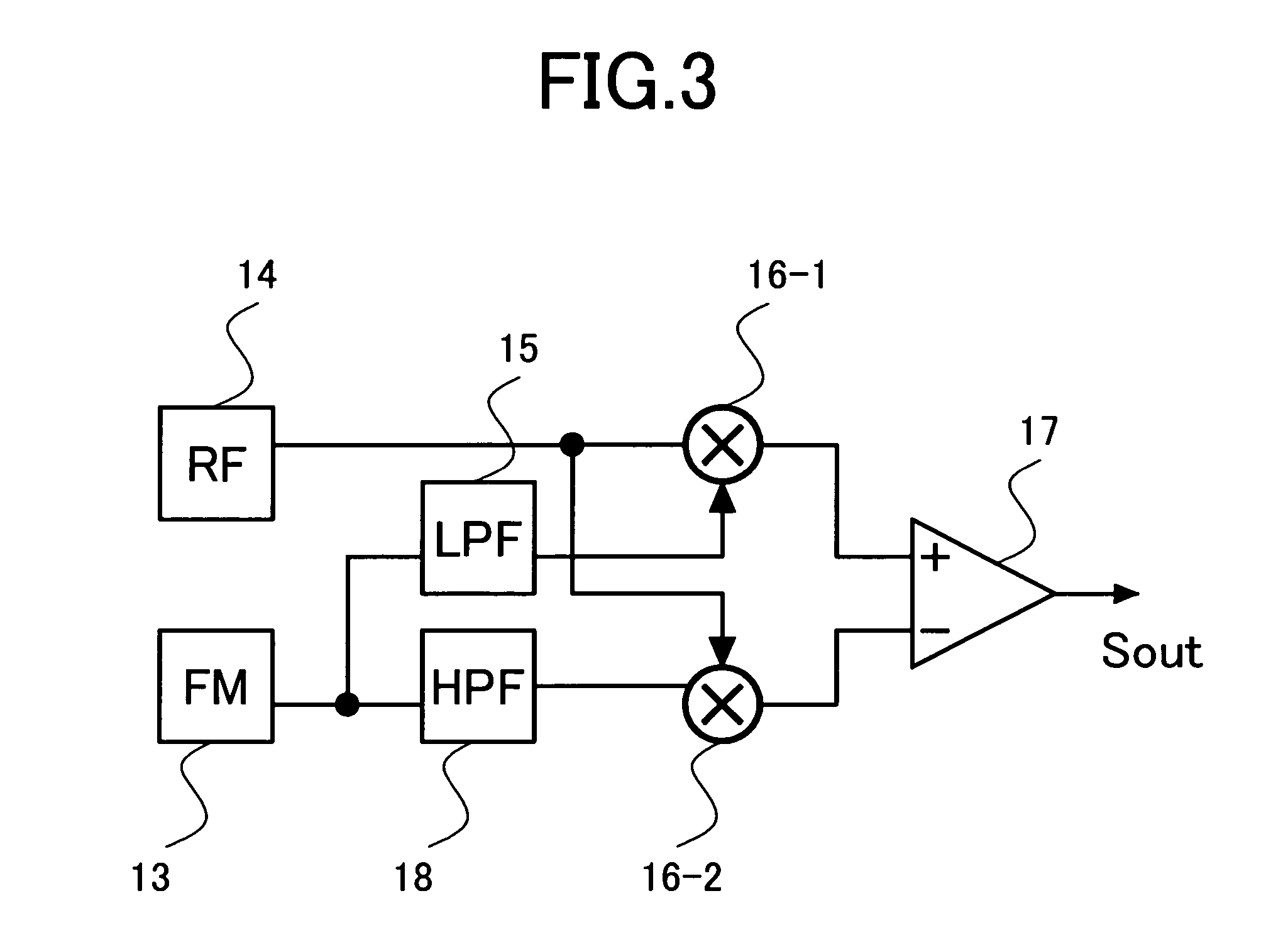
[0043] Those APC operations are realized by monitoring the optical output power at a front monitor 13 as shown in FIG. 10 and feeding back the output power to an LD driver...


PUM


Abstract

Disclosed herewith is a data recording and reading equipment capable of reducing laser noise easily. At first, a laser beam source that can reduce the laser noise when reading data from a subject optical disk is obtained. A modulator capable of varying laser attenuation with a voltage is disposed so as to precede the laser, thereby the laser noise when reading data from the optical disk can be reduced without lowering the laser power when in writing.

Description

CLAIM OF PRIORITY [0001] The present application claims priority from Japanese application JP 2004-341380 filed on Nov. 26, 2004, the content of which is hereby incorporated by reference into this application. FIELD OF THE INVENTION [0002] The present invention relates to a data recording and reading equipment such as any of optical disk drives of CD-R, CD-RW, DVD-R, DVD-RW, DVD-RAM, Blu-Ray disk, and HD-DVD for driving / controlling laser beam waveforms when recording / reading data on / from data recording media. BACKGROUND OF THE INVENTION [0003] Such optical recording disk drives have all been expanded in capacity and CD drives using conventional infrared laser beams (wavelength: 780 nm), DVD drives using red laser beams (wavelength: 650 nm), and blu-ray disk drives (BD) and high density (HD) DVD drives using blue laser beams are already under manufacturing. In optical disk drives such as optical disk reading / recording drives as described above, each high frequency signal (read RF sig...

Claims


Application Information

Patent Timeline
IPC IPC(8): G11B5/09
CPCG11B7/1263G11B7/127G11B7/128
Inventor WATANABE, KOICHIKUROKAWA, TAKAHIROAOKI, MASAHIROSHIMANO, TAKESHI
Owner HITACHI LTD
Why Eureka
Try Eureka