
Modular infrared irradiation apparatus and its corresponding monitoring devices

a module infrared irradiation and monitoring device technology, applied in the direction of heating types, combustion processes, domestic heating details, etc., can solve the problems of loss of control of flame and equipment explosion, reducing process efficiency, and inner burning, so as to enhance the global efficiency of thermal energy and improve control during operation.

Inactive Publication Date: 2006-06-01
CAMARGO RANGEL PAULO GERAIS DE
View PDF3 Cites 12 Cited by
  • Summary
  • Abstract
  • Description
  • Claims
  • Application Information

AI Technical Summary

Benefits of technology

[0024] According to the above discussed and in view of the above mentioned problems, the present invention provides a modular IR irradiation apparatus which employs combustion gas and its respective integrating devices for automatically control the air / gas mixture, for sequencing the process starting, for interlocking the equipment and the corresponding process. Some modifications in the irradiation modules have been done in order to eliminate shadow zones and to enhance gas flowability; such improvements are achieved by means of a fibrous ceramic. The fibrou ceramic have flexible pores through which the air / gas mixture flows and after the air / gas mixture emerges from an escape surface an ignition means is driven and a fire line provided and kept stable over the ceramic escape surface which acts as IR irradiation element at high frequency bands.

Problems solved by technology

Ceramic plates of the art tend to “swallow” the flame causing an inner burning and reducing the efficiency of the process and / or loss of the control of the flame and equipment explosion.

Method used


Image

  • Modular infrared irradiation apparatus and its corresponding monitoring devices
  • Modular infrared irradiation apparatus and its corresponding monitoring devices
  • Modular infrared irradiation apparatus and its corresponding monitoring devices

Examples


Embodiment Construction

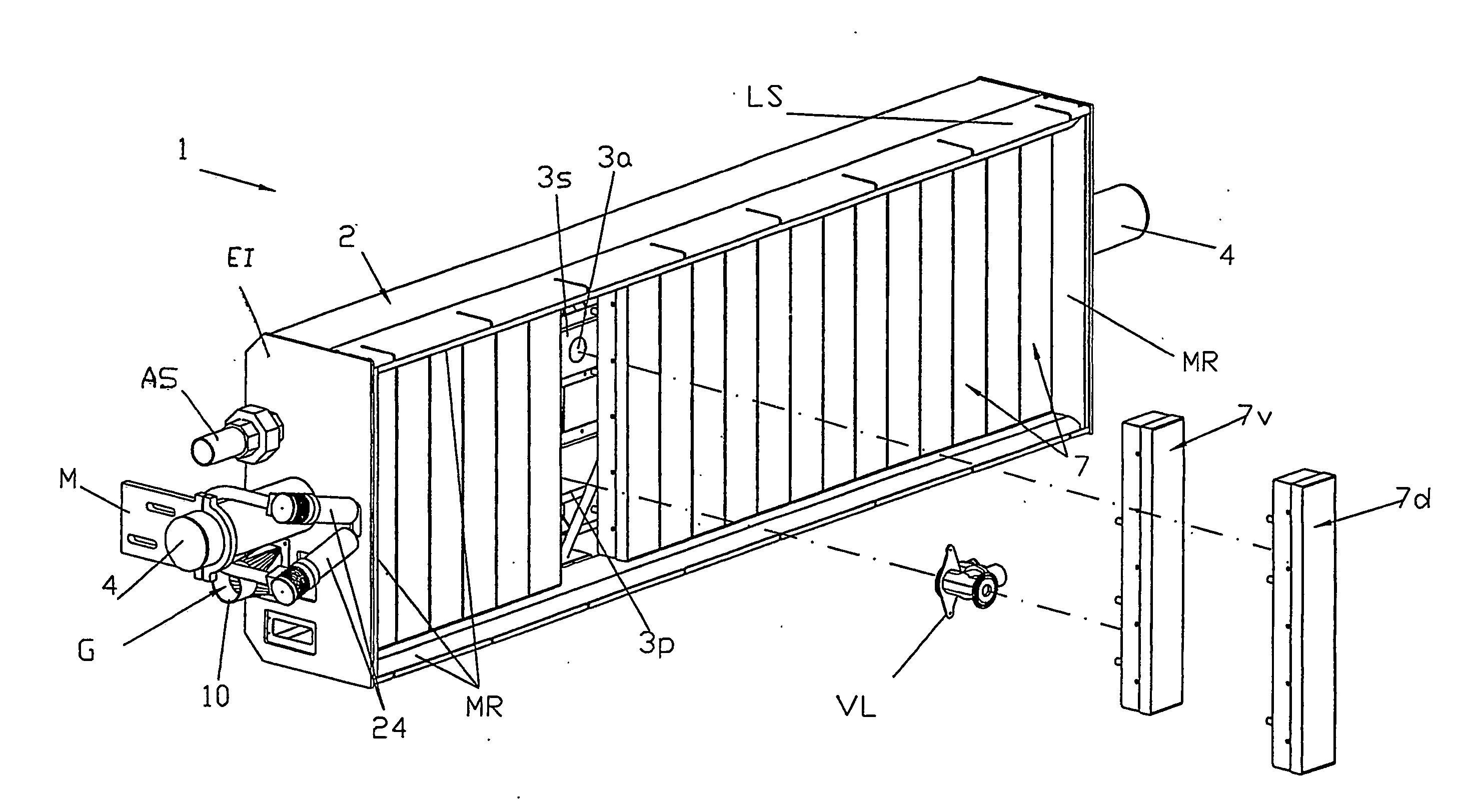
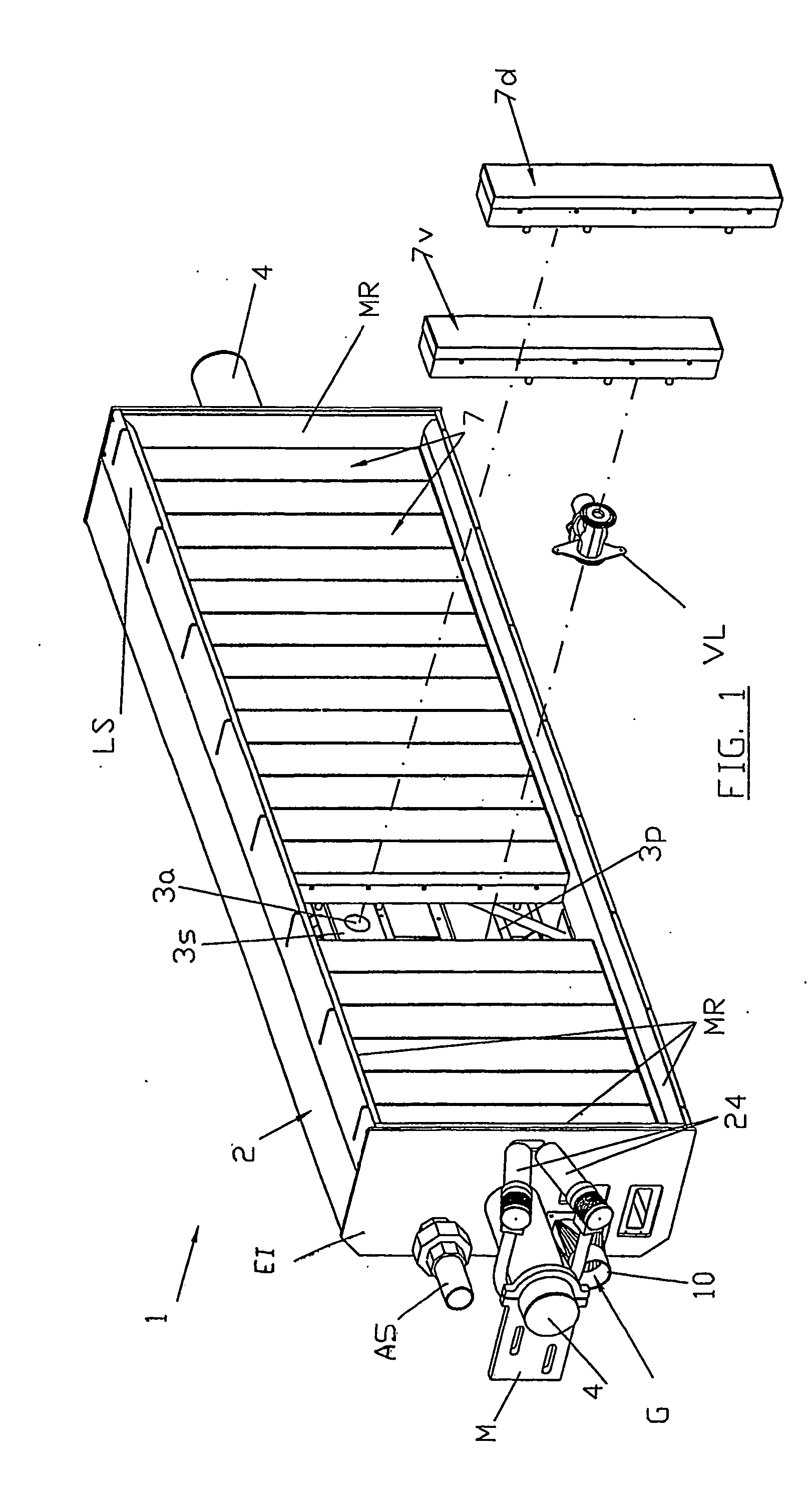
[0053] Referring to the Figures, the present invention refers to a MODULAR INFRARED IRRADIATION APPARATUS AND ITS CORRESPONDING MONITORING DEVICES, the modular heat irradiation apparatus (1) is directed to heat transfer operation involving elevated rates of heat to be contoinously traferred to a receiving substrate, e.g., industrial drying process of fibrous products as paper or cellulose (L) (FIG. 2).

[0054] According to the present invention and FIGS. 1 and 2, the modular heat irradiation apparatus basically comprises a metallic frame or bed (2) which is designed for receive a number of irradiation modules (7), according to process width and in such manner to receiver distribution and support ducts, priamary plenum (3p), secondary plenum (3s) which possesses gas / ar (G) mixture feeding outlets (3a) to the modules (7).

[0055] The employment of two plena having rectangular shape (3p and 3s) serve as mechanic support fo the modules (7) in order to position them in such manner to permi...


PUM


Abstract

Heat irradiation apparatus (1) defined in terms of the following:—Refractory flexible irradiation module (7) comprising stopping means which are high temperature resistant and avoid shadow zones and side losses of heat at the burning zone in the ceramic surface;—Employment of refractory flexible ceramic plates (15) having flexible pores which permit air / gas modulation, the flexible pores permit define the path of the air / gas mixture through the ceramic plate (15). When the flow pressure of mixture is reduced, part of the pore automatically close and the combustible mixture is conducted to the surface where the hot fibers are placed. The fibres keep the combustion active at the surface, multiplying IR heating effects. Ceramic plates (15) of the art tend to “swallow” the flame causing an inner burning and reducing the efficiency of the process and / or loss of the control of the flame and equipment explosion.—Sensors and measuring means are provided for monitoring all steps: Thermal sensor (14)—safety device applied in the lower face of each flexible fibrous ceramic module (15), more particularly fixed in the support screen of the ceramic plate (15) and extending to median line of such plate (15), for monitoring a possible heat flow inversion due to external factors which cause the “flame swallowing”. The apparatus further comprises oxygen measuring means (23) and an ultraviolet flame detector (24).

Description

FIELD OF THE INVENTION [0001] The present invention refers to a modular infrared irradiation apparatus which employs combustion gas and its respective monitoring devices. Particularly, the apparatus of the present invention is direcetd to thermal transfer operations for provide quick and efficient thermal energy transfers at high rates as in industrial drying operations of paper making and cellulose industries. The irradiation apparatus comprises automation means for control the starting and all steps of the procedure which is performed by such equipment and permits multiple industrial applications. BACKGROUND OF THE INVENTION [0002] Technicians of the art, particularly those skilled in the continous fibrous products manufacturing processes, know that a drying step (or a set drying steps distributed along the process) is a necessary step for drying coating or impregnating substances added to the product. [0003] Known drying techniques employ heat transfer by direct contact between t...

Claims


Application Information

Patent Timeline
IPC IPC(8): F23N5/08F23D14/12D21F5/00F23D14/16F24C15/24F26B3/30G01N21/00H05B3/00H05B6/00
CPCD21F5/002F23D14/16F23D2203/105F23D2212/103F23N5/08F26B3/305H05B3/0038H05B2203/032F23D2212/10
Inventor CAMARGO, RANGEL PAULO GERAIS DE
Owner CAMARGO RANGEL PAULO GERAIS DE
Learn More