Wheel support hub unit, bearing ring member for wheel support hub unit, and method of manufacturing the same

Active Publication Date: 2006-06-08
NSK LTD
View PDF6 Cites 17 Cited by
  • Summary
  • Abstract
  • Description
  • Claims
  • Application Information

AI Technical Summary

Benefits of technology

[0045] According to the present invention, the fixing portions are formed with the shaft portion in one body by the cold side extrusion. Therefore, even when the extrusion length, i.e. the area of the fixing portions increases, the forming load does not vary, and the forming operation can be carried out with a small load as compared with the case where the fixing portions are compression formed. This enables the forming operation to be carried out by using comparatively small equipment by the cold forging, a cutting margin occurring in the later stage to be reduced, and the inexpensive bearing ring member and wheel support hub unit to be obtained. Furthermore, a joint portion between the fixing portions and an outer circumferential portion of the bearing ring member is not subjected to a bending process, so that a sufficient thickness can be secured in the joint portion. This enables the bearing member and wheel support hub unit having a sufficient strength to be obtained.
[0046] Since the fixing portions are formed by the sideway extrusion, the extrusion remaining portion can be used as the positioning cylindrical portion. Therefore, the circumferentially continuous positioning cylindrical portions can be formed easily and highly accurately with the shaft portion in one body. When the positioning cylindrical portion is formed separately, a required fixing excess thickness becomes unnecessary, and a material yield in the condition in which the thickness of the required portion is secured can be improved. This enables the manufacturing cost to be reduced.
[0047] According to the present invention, the bearing ring member is formed by the cold forging including a step of extrusion forming out of a solid or hollow shaft raw material a shaft portion and a head portion having a shape of an inner circumference of a positioning cylindrical object, and a upsetting step for forming fixing portion by upsetting the head portion with the height of the fixing portions kept thereon, by using a die provided with a bore the diameter of which corresponds to that of an outer circumference of the positioning cylindrical portion. Therefore, when the upset-form

Problems solved by technology

However, in the hot forging process, the dimensional accuracy is low, and a decarbonization removal operation is necessary in some cases in a thermal treatment unit.
Since a large cutting margin is necessary in a later process, the manufacturing cost increases.
However, in the invention disclosed in the above Patent Publication 1, a bending process is carried out when a joint portion between the fixing flanges, which need the highest strength, and the outer circumferential portion of the bearing ring member is cut and raised, flaws, such as cracks being liable to occur, the strength of the joint portion becoming unstable.
Moreover, since the joint portion has to be rendered easily bendable, it is impossible to reinforce this portion by, for example, increase the thi

Method used


Image

  • Wheel support hub unit, bearing ring member for wheel support hub unit, and method of manufacturing the same
  • Wheel support hub unit, bearing ring member for wheel support hub unit, and method of manufacturing the same
  • Wheel support hub unit, bearing ring member for wheel support hub unit, and method of manufacturing the same

Examples


first embodiment

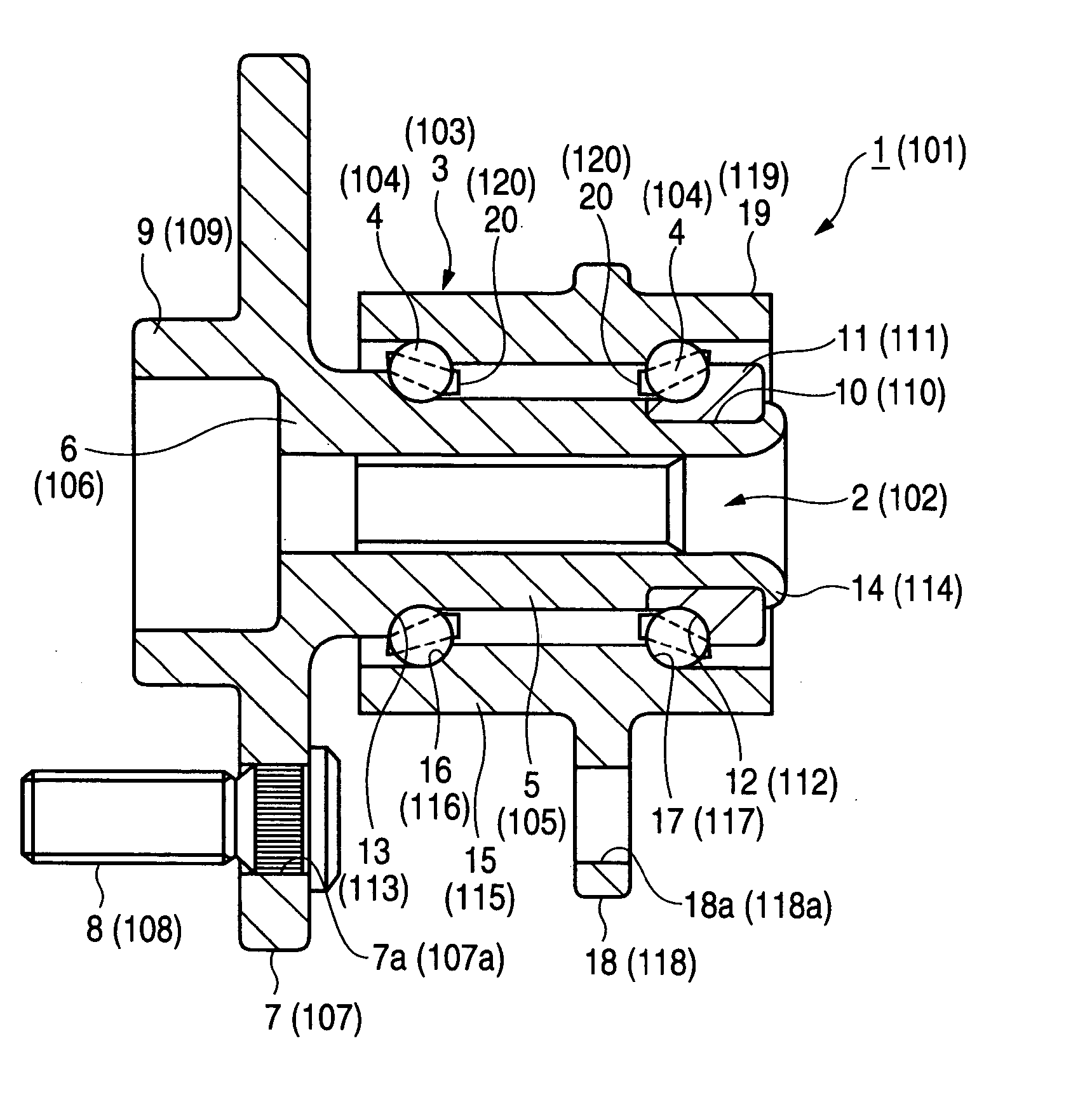
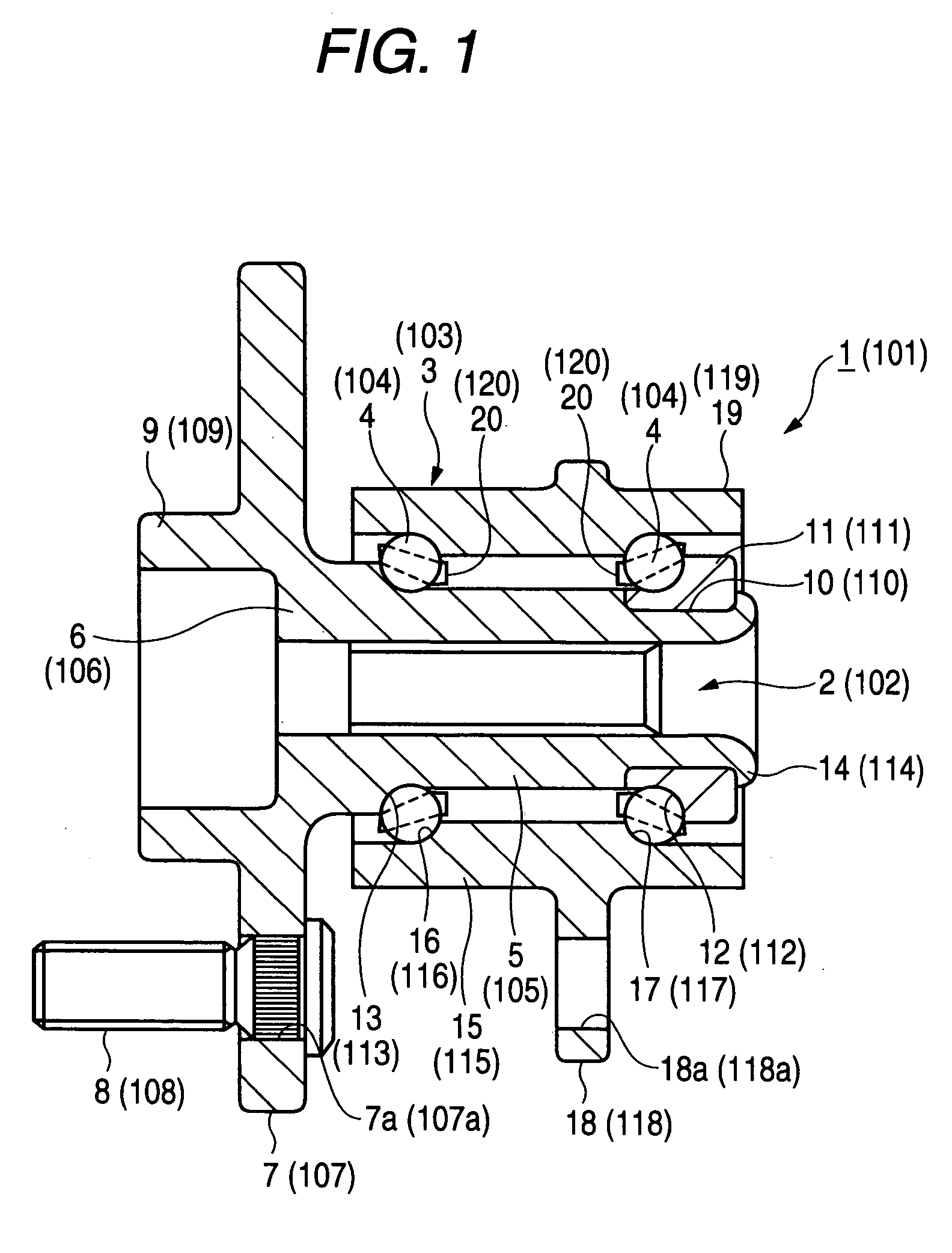
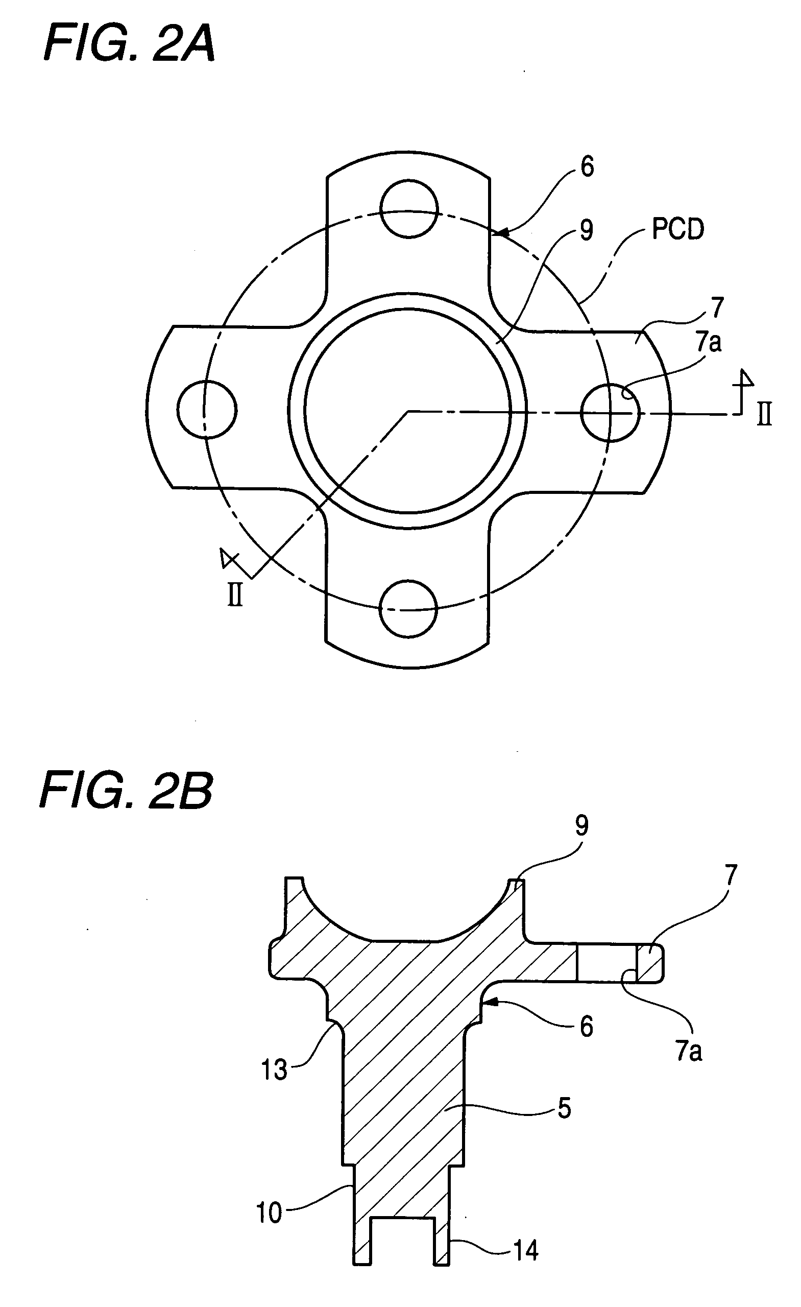
[0069] As shown in FIGS. 1 to 3, a wheel support hub unit 1 is used as a driven wheel, and provided with a bearing unit having a hub (inner member) 2, an outer ring (outer member) 3 as a bearing ring member, and a plurality of rolling elements 4.

[0070] The hub 2 is provided with a hub wheel 6 including a solid shaft portion 5 as a bearing ring member. The hub wheel 6 is provided at an outboard-side end portion (outer end portion (left end portion in FIG. 1) in the widthwise direction of the vehicle in a vehicle combined state) of the outer circumferential surface thereof with wheel fixing flanges 7 constituting the fixing portions extending in the radially outward direction which crosses the shaft portion 5 at right angles thereto. The wheel fixing flanges 7 are provided on the outboard-side surface thereof with a plurality of studs 8 implanted therein at substantially equal intervals so as to fix a wheel, brake rotors and the like thereto. Each of the wheel fixing flange 7 is prov...

second embodiment

[0093] The hub ring 106 for a driving wheel, which is a bearing ring member of the wheel support hub unit 101 will be taken as an example, and a method of manufacturing the same will be described. First, as shown in FIG. 10A, a hollow cylindrical shaft portion raw material 130 is subjected to forward extrusion forming to form a shaft portion member 130a of FIG. 10B. A head portion of the shaft portion member 130a member is then upset to form a shaft portion member 130b shown in FIG. 1C. This shaft portion member 130b is subjected to a head portion rearward extrusion forming to form a head portion 132 having a stepped recess 131 forming the shapes of the inner circumferences of the shaft portion 105 and positioning cylindrical portion 109. The head portion 132 is then upset so that that the height of the wheel fixing flanges 107 remains by using the form 140 shown in FIG. 11, to form the wheel fixing flanges 107.

[0094] The form 140 is provided with a lower die 141 having an inner ci...

third embodiment

[0100] A method of manufacturing a bearing ring member of a wheel support hub unit in a third embodiment of the present invention will now be described in detail with reference to FIG. 12 with the outer ring 103 for the driving wheel in the second embodiment as a bearing ring member.

[0101] As shown in FIG. 12A, a hollow cylindrical shaft portion raw material 150 is subjected to the forward extrusion forming to form a shaft portion member 150a having a head portion 152 provided with a recess 151 forming an inner circumferential shape of a shaft portion 115 and positioning cylindrical portion 119 of FIG. 12B. As shown in FIG. 12C, a head portion 152 is then formed to a heteromorphous outer circumferential shape having radial projections 153 the number of which is equal to that of fixing holes 118a provided in a suspension unit fixing flanges 118. In the upsetting step of FIG. 12D, the head portion 152 is then upset with the shaft portion 115 held in the lower die (not shown) and with...


PUM

PropertyMeasurementUnit
Thicknessaaaaaaaaaa
Heightaaaaaaaaaa

Abstract

A raceway member 6 of a wheel support hub unit, having wheel or vehicle body fixing portions 7 extending radially outward from a solid or hollow shaft portion, and a wheel or vehicle body positioning cylindrical portion 9 extending concentrically with the shaft portion, the fixing portion 7 being formed by the cold side extrusion so that the fixing portion is integral with the shaft portion 5.

Description

BACKGROUND OF THE INVENTION [0001] The present invention relates to a wheel support hub unit adapted to support rotatably a wheel of, for example, an automobile on a suspension unit, a bearing ring member for a wheel support hub unit, and a method of manufacturing the same. [0002] A wheel of an automobile and the like is supported rotatably on a wheel support hub unit fixed to a suspension unit for a vehicle body. The wheel support hub unit is provided with a plurality of rolling elements interposed between an inner member and an outer member, which have raceway surfaces, the inner member and outer member being provided with fixing flanges to be fixed to the suspension unit for the wheel or vehicle body. A positioning unit adapted to position the wheel is provided on a side of the fixing flanges. [0003] When the inner member and outer member as bearing ring members are manufactured, the surface area of the fixing flanges is large, and a very large forming load is needed in the cold ...

Claims


Application Information

Patent Timeline
IPC IPC(8): F16C33/00
CPCB21K1/40B60B27/00B60B27/0005B60B27/0084B60B27/0094Y10T29/49533F16C33/64B21J5/02F16C2326/02Y10T29/49689Y10T74/20696F16C19/186
Inventor KOBAYASHI, KAZUTOOOTUKA, KIYOSHIYASUDA, YUUMORI, KOUHEI
Owner NSK LTD
Why Eureka
Try Eureka