
Atmospheric pressure charged particle discriminator for mass spectrometry

Inactive Publication Date: 2006-06-08
MDS SCIEX
View PDF23 Cites 20 Cited by
  • Summary
  • Abstract
  • Description
  • Claims
  • Application Information

AI Technical Summary

Benefits of technology

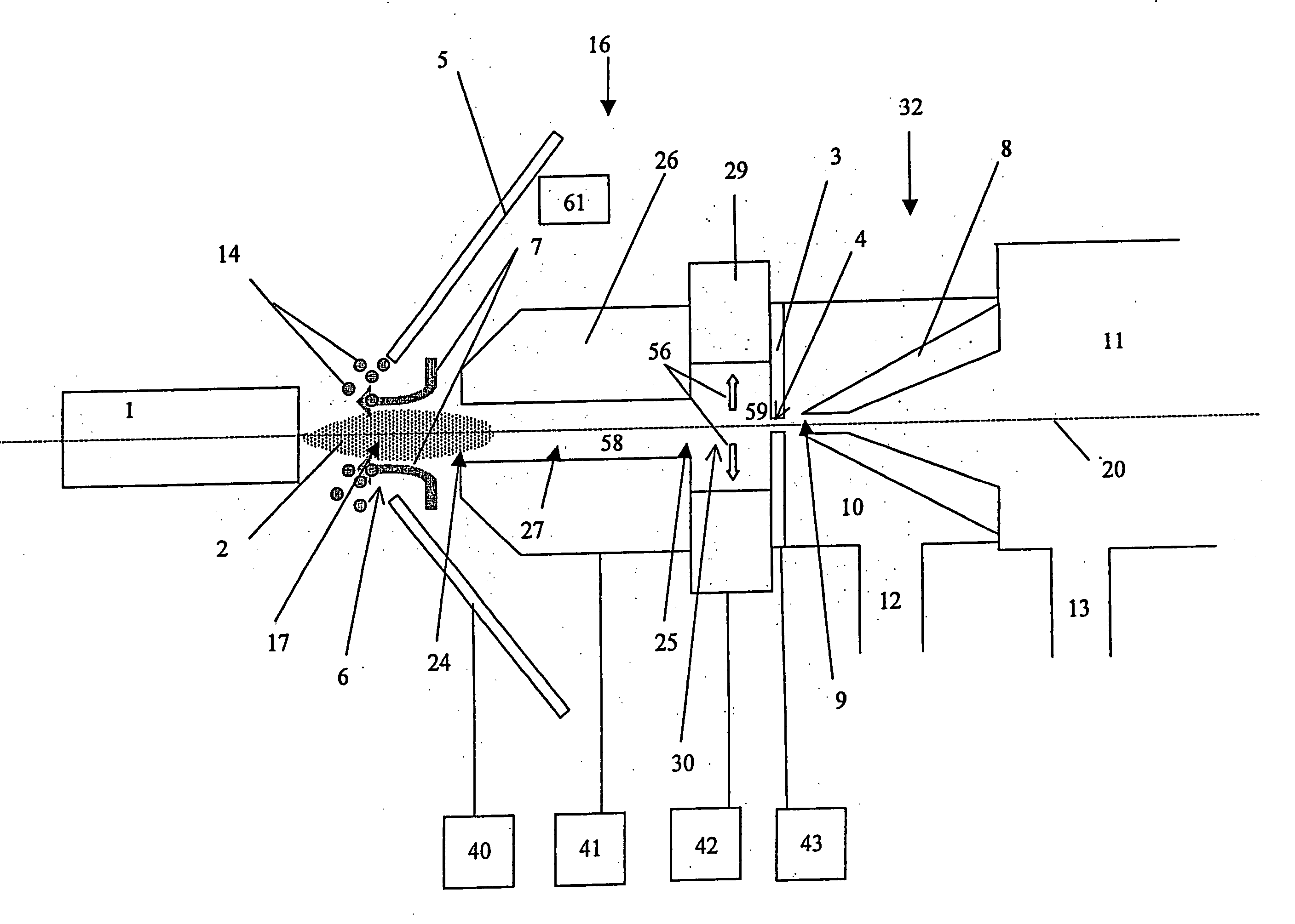
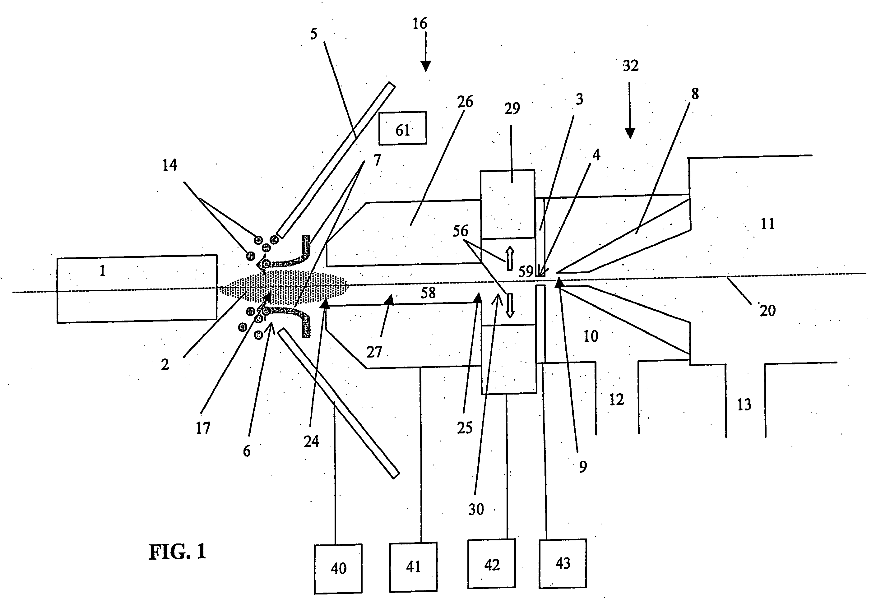
[0011] In an embodiment where the atmospheric pressure ion source is an electrospray ion source, the entrance cell may function as a desolvation cell. The electrospray ion source operates in the atmosphere and provides a spray of charged droplets that contain ions to be studied. The spray is directed into a heated bore of the desolvation cell for drying the droplets in the spray to generate an ion stream, which contains undesirable particulates. A particle discrimination cell for discriminating against (i.e., removing) particulates is disposed downstream of the desolvation cell and before an aperture in a partition that separate the atmospheric pressure from the vacuum in the vacuum chamber. The particle discrimination cell has a bore for receiving the ion stream that is larger than the bore of the desolvation cell and has a central zone and a discrimination zone surrounding the central zone. Eddies are formed in the discrimination zone when the ion stream flows into the bore of the particle discrimination cell. The particle discrimination cell has a voltage applied thereto for generating a particle discrimination electric field in its bore. The electric field and the formation of eddies in the particle discrimination cell together provide the effect of removing particulates from the ion stream so that they do not enter the aperture of the partition.
[0012] The present invention also provides a method of interfacing an ion source that operates in the atmosphere with an ion mass spectrometer in a vacuum chamber. The ion source may be, for instance, an electrospray source or a MALDI source. An interface that contains an entrance cell and a charged particle discrimination cell is disposed between the atmospheric ion source and the vacuum chamber. When the ion source is an electrospray source, the entrance cell is used as a desolvation cell. A spray of charged ion droplets generated by the ion source is directed into a heated bore of a desolvation cell for drying the droplets in the spray to generate an ion stream, which contains undesirable particulates. The ion stream then is directed through a discrimination cell that is disposed downstream of the desolvation cell and upstream of an aperture in a partition that separates the atmosphere from the vacuum chamber containing the ion mass spectrometer. The discrimination cell has a bore that is greater than the bore of the desolvation cell and has a central zone and a discrimination zone surrounding the central zone. While flowing from the desolvation cell into the discrimination cell, the ion stream generates eddies in the discrimination zone of the discrimination cell. A voltage is applied to the discrimination cell to generate a discrimination electric field in the bore of the discrimination cell. The electric field and generation of eddies in the discrimination cell together provide the effect of removing undesirable charged particulates from the ion stream so that they do not enter the aperture of the partition.

Problems solved by technology

Consequently, after desolvation, there is a size distribution for desolvated particles where there are large and heavy charged particles that may contaminate the aperture or conductance limit, thereby preventing the long-term stable operation of the mass analysis region, and / or introducing additional noise to the ion detector.
This additional source of noise reduces the signal to nose ratio and thus, the sensitivity of the mass spectrometer.
In addition, the desolvation of ions is also affected by the diameter of the tube due to changes in residence time.
These particulates or droplets can accumulate in the small bore, which may cause blockage or they may pass through the small bore and enter the vacuum chamber leading to extensive contamination.
That is, this arrangement will only prevent undesolvated droplets and particulates traveling along the central axis from entering the orifice.
An offset of the desolvation tube will not prevent droplets and charged particulates aligned with the offset location from entering the skimmer or to prevent an accumulation from building up around the orifice.
It is expected that significant loss of ion current to the walls of this chamber would occur in addition to obvious inefficiency of sampling from only one point of cylindrical flow through the exit aperture.
The plume of ions generated by each laser pulse contains not only the analyte ions but also charged particulates containing the matrix material, which may affect the performance of the mass spectrometer if not removed from the ion stream.

Method used


Image

  • Atmospheric pressure charged particle discriminator for mass spectrometry
  • Atmospheric pressure charged particle discriminator for mass spectrometry
  • Atmospheric pressure charged particle discriminator for mass spectrometry

Examples


Embodiment Construction

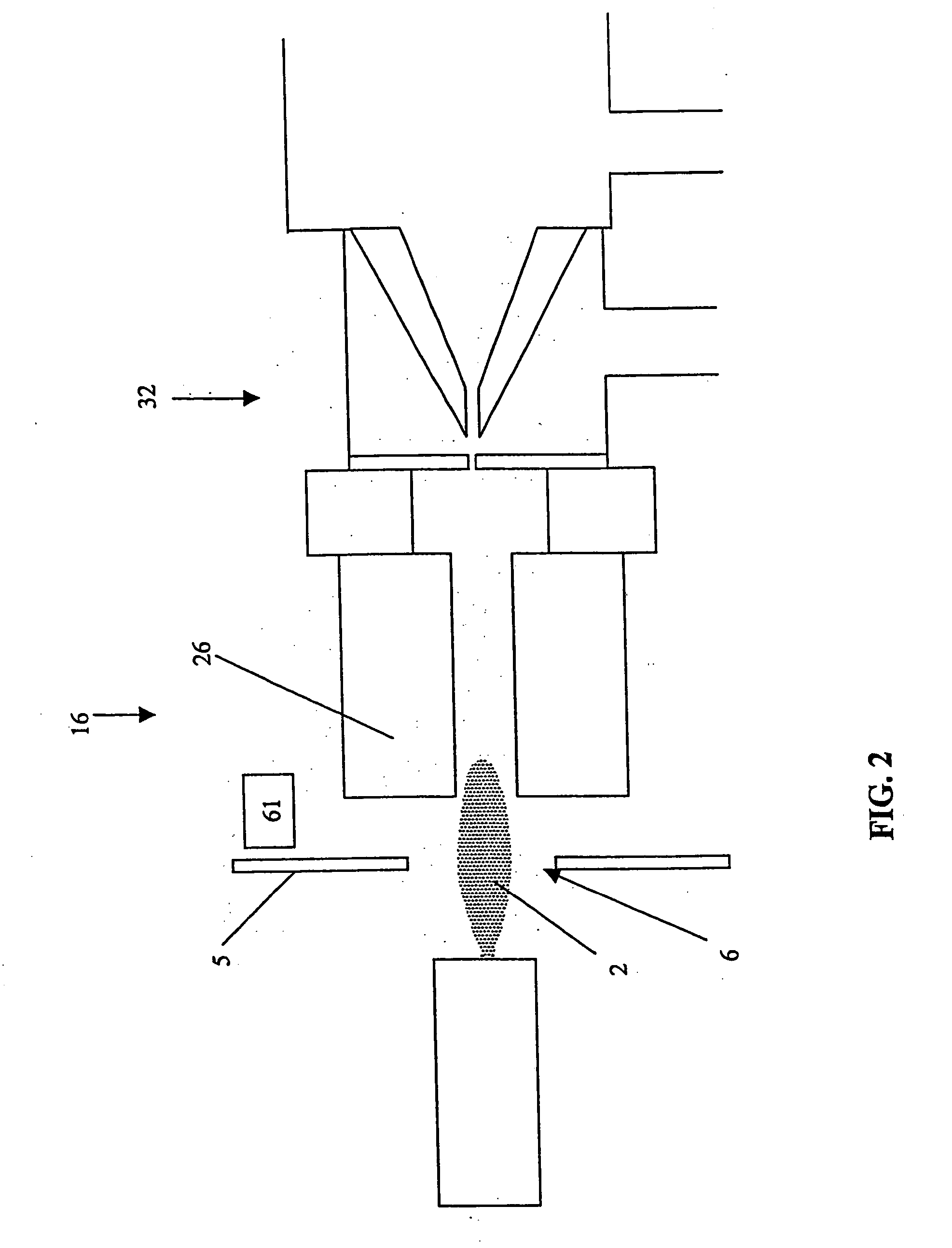
[0023] Referring now to the drawings, FIG. 1 is an illustration according to one embodiment of the present invention, which shows an atmospheric pressure interface generally indicated by 16. The interface 16 is positioned between an ion source 1 and the mass spectrometer 32, the interface 16 comprising of at least one interface cell, described as follows. Ions from the ion source 1 pass into the mass spectrometer 32 comprising of vacuum chambers 10 and 11 through apertures 4 and 9, respectively. The pressure in each of the vacuum chambers 10 and 11 is step-wise reduced by vacuum pumps 12 and 13, respectively. The aperture 9 mounted in the partition 8 between the vacuum stages restricts neutral gas conductance from one pumping stage to the next while the aperture 4 mounted in the partition 3 restricts the flow of gas from atmosphere into the vacuum chamber 10. The pressure between the aperture 4 and the ion source 1 is typically at or near atmospheric pressure.

[0024] The ion source ...


PUM


Abstract

An apparatus and method for performing mass spectroscopy uses an ion interface to provide the function of removing undesirable particulates from an ion stream from an atmospheric pressure ion source, such as an electrospray source or a MALDI source, before the ion stream enters a vacuum chamber containing the mass spectrometer. The ion interface includes an entrance cell with a bore that may be heated for desolvating charged droplets when the ion source is an electrospray source, and a particle discrimination cell with a bore disposed downstream of the bore of the entrance cell and before an aperture leading to the vacuum chamber. The particle discrimination cell creates gas dynamic and electric field conditions that enables separation of undesirable charged particulates from the ion stream.

Description

CROSS-REFERENCE TO RELATED PATENT APPLICATION [0001] This application claims the priority of U.S. Provisional Application 60 / 447,655, filed Feb. 14, 2003.FIELD OF THE INVENTION [0002] This invention relates to mass spectrometry, and more particularly to the interface between an atmospheric pressure ion source and low pressure regions of a mass spectrometer. BACKGROUND OF THE INVENTION [0003] Samples or analytes for analysis in mass spectrometers are often ionized in an atmospheric environment, and the ions are then introduced into a vacuum chamber that contains the mass spectrometer. An atmospheric pressure ion source provides advantages in handling of samples, but the introduction of ions from the ion source into the vacuum chamber often requires a proper interface disposed between the ion source and the vacuum chamber. For instance, one common family of ionization techniques includes electrospray and its derivatives, such as nanospray, which provides a low flow. In all such techni...

Claims


Application Information

Patent Timeline
IPC IPC(8): B01D59/44G01N30/72H01J49/00H01J49/04H01J49/16
CPCH01J49/044H01J49/06
Inventor SCHNEIDER, BRADLEYCOVEY, THOMAS R.
Owner MDS SCIEX
Learn More