

Material for organic electroluminescent device, organic electroluminescent device, illuminating device and display
a technology of organic electroluminescent elements and illuminating devices, which is applied in the direction of discharge tube luminescnet screens, natural mineral layered products, etc., and can solve the problems of nitrogen-containing aromatic heterocyclic compounds, organic electroluminescent elements exhibiting phosphorescent emission, and insufficient emission efficiency in other color emission
- Summary
- Abstract
- Description
- Claims
- Application Information
AI Technical Summary
Benefits of technology
Problems solved by technology
Method used
Image

Examples
example 1
>
[0211] A pattern was formed on a substrate (100 mm×100 mm×1.1 mm) composed of a glass plate and a 100 nm ITO (indium tin oxide) layer (NA45 manufactured by NH Technoglass Co., Ltd.) as an anode. Then the resulting transparent substrate having the ITO transparent electrode was subjected to ultrasonic washing in isopropyl alcohol and dried by a dry nitrogen gas and subjected to UV-ozone cleaning for 5 minutes. Thus obtained transparent substrate was fixed on a substrate holder of a vacuum deposition apparatus available on the market. Further, 200 mg of α-NPD was placed in a first resistive heating molybdenum boat, 200 mg of exemplified compound 39 was put in a second resistive heating molybdenum boats 200 mg of B-Alq was placed in a third resistive heating molybdenum boat, 100 mg of Ir-1 was placed in a fourth resistive heating molybdenum boat, and 200 mg of Alq3 was placed in a fifth resistive heating molybdenum boat.
[0212] The resulting boats were set in the vacuum deposition appa...
example 2
>
[0220] A pattern was formed on a substrate (100 mm×100 mm×1.1 mm) composed of a glass plate and a 100 nm ITO (indium tin oxide) layer (NA45 manufactured by NH Technoglass Co., Ltd.) as an anode. Then the resulting transparent substrate having the ITO transparent electrode was subjected to ultrasonic washing in isopropyl alcohol and dried by a dry nitrogen gas and subjected to UV-ozone cleaning for 5 minutes. Thus obtained transparent substrate was fixed on a substrate holder of a vacuum deposition apparatus available on the market. Further, 200 mg of α-NPD was placed in a first resistive heating molybdenum boat, 200 mg of exemplified compound 13 was put in a second resistive heating molybdenum boat, 200 mg of exemplified compound 39 as a hole blocking material was placed in a third resistive heating molybdenum boat, 100 mg of Ir-1 was placed in a fourth resistive heating molybdenum boat, and 200 mg of Alq3 was placed in a fifth resistive heating molybdenum boat.
[0221] The resultin...
example 3
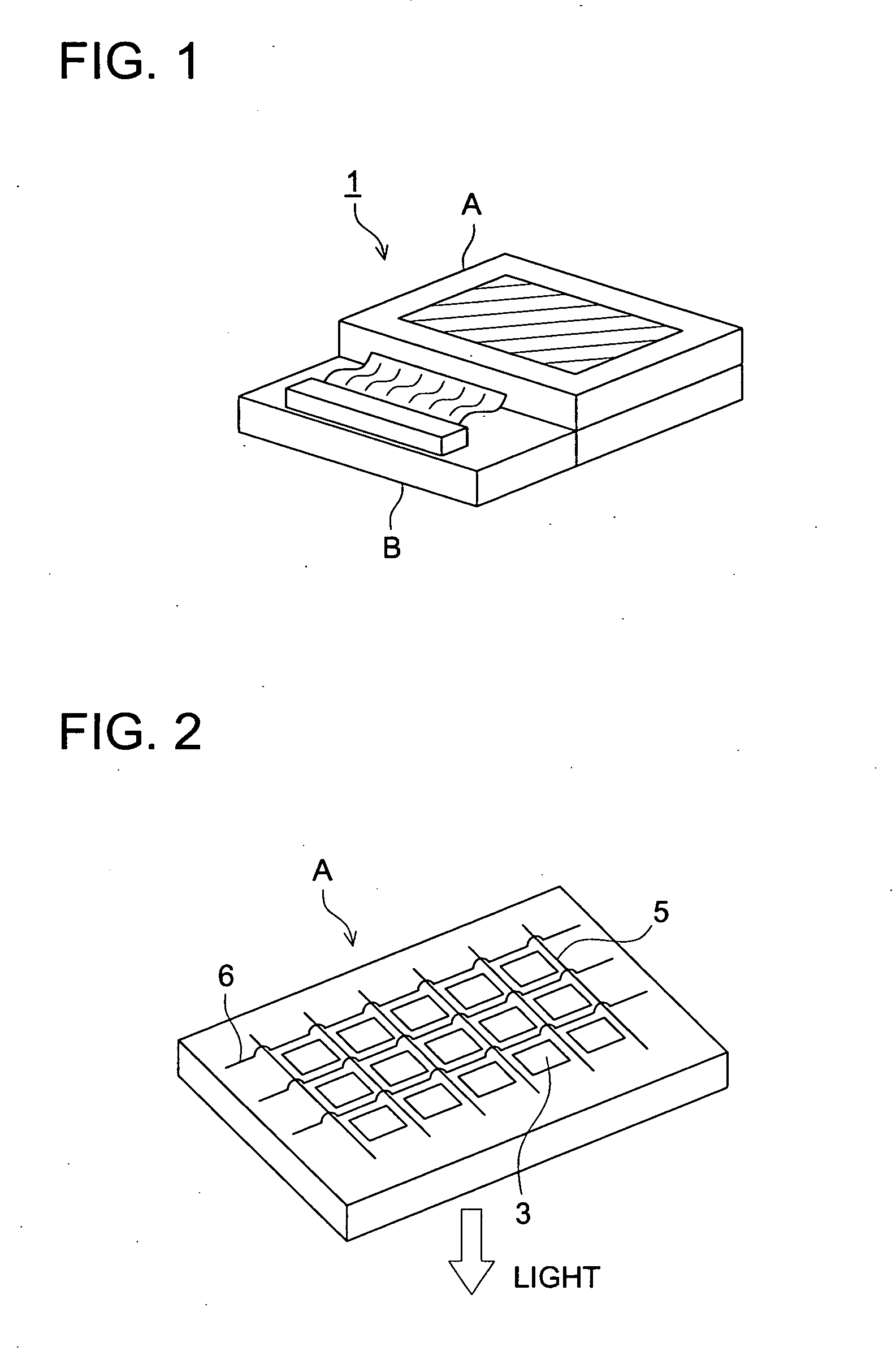
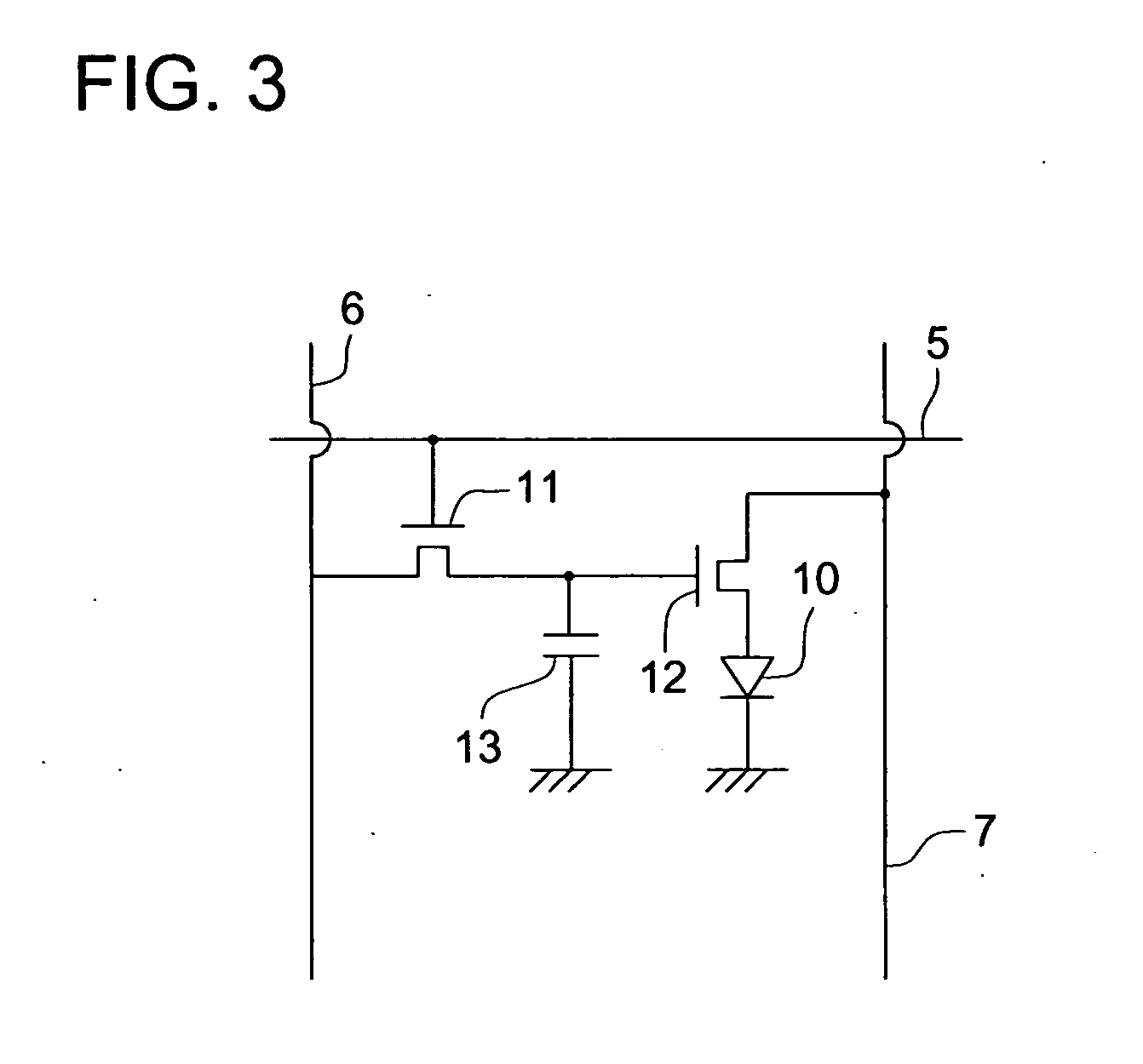
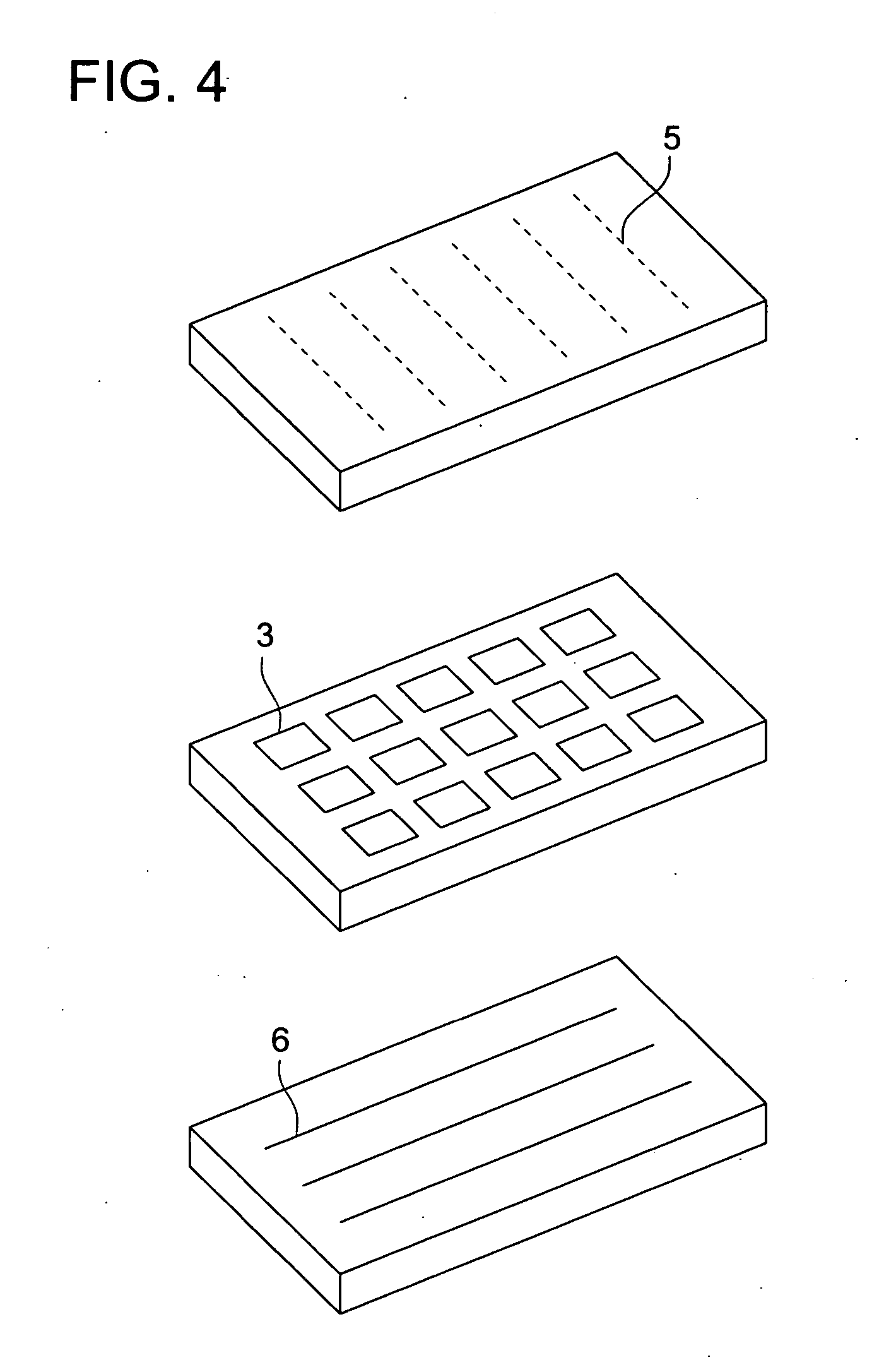
[0225] Red light emitting organic EL elements prepared in the same manner as Organic EL elements Nos. 2-1 and 2-4 in EXAMPLE 2 of the present invention, except that the phosphorescent compound was replaced by Ir-9 and a blue light emitting organic EL element prepared in the same manner as Organic EL Element No. 2-4, except that the phosphorescent compound was replaced by Ir-12 were prepared. These organic EL elements were juxtaposed on the same substrate to prepare a full color display device driven by an active matrix method, illustrated in FIG. 1. In FIG. 2, a schematic drawing of only display section A is shown. Namely, on the same substitute, a wiring section containing plural scanning lines 5 and plural data lines 6 and juxtaposed plural pixels 3 (pixels emitting red light, pixels emitting green light and pixels emitting blue light) are provided. The plural scanning lines 5 and plural data lines 6 are composed of an electroconductive material. The lines 5 and the lines 6 are cr...
PUM
| Property | Measurement | Unit |
|---|---|---|
| external quantum efficiency | aaaaa | aaaaa |
| external quantum efficiency | aaaaa | aaaaa |
| internal quantum efficiency | aaaaa | aaaaa |
Abstract
Description
Claims
Application Information