Internal combustion engine

a technology of internal combustion engine and combustion chamber, which is applied in the direction of machines/engines, output power, oscillatory slide valves, etc., can solve the problems of limiting the designers' options on how the engine is placed within the vehicle, reducing the height profile, and reducing the weigh

Inactive Publication Date: 2006-06-15
ADVANCED PROPULSION TECH
View PDF84 Cites 39 Cited by
  • Summary
  • Abstract
  • Description
  • Claims
  • Application Information

AI Technical Summary

Benefits of technology

[0015] Embodiments of the present invention provide a two cylinder two-stroke internal combustion engine having improved efficiency, a reduced height pro

Problems solved by technology

An improvement in one of these areas at the expense of any other is commercially unacceptable.
Despite the promise of external continuous combustion technologies such as Stirling engines or fuel cells with electric motors to eventually provide low-emission high-efficiency engines for automobiles and light aircraft, these technologies will not be viable alternatives to internal combustion engines in the foreseeable future due to their inherent disadvantages in weight, space, drivability, energy density and cost.
The need for at least four cylinders to achieve a suitable rate of power stroke production dictates the size and shape of this engine, and therefore also greatly limits the designers' options on how the engine is placed within the vehicle.
The small cylinders of these engines are typically not optimal for efficient combustion or the reduction of raw emissions.
The four cylinder in-line configuration also has drawbacks with respect to passenger comfort, since there are significant unbalanced free-mass forces which result in high noise and vibration levels.
Two-stroke engines, however, have seen lim

Method used


Image

  • Internal combustion engine
  • Internal combustion engine
  • Internal combustion engine

Examples


Embodiment Construction

[0053] In the following detailed description, reference is made to the accompanying drawings which form a part hereof wherein like numerals designate like parts throughout, and in which is shown by way of illustration specific embodiments in which the invention may be practiced. It is to be understood that other embodiments may be utilized and structural or logical changes may be made without departing from the scope of the present invention. Therefore, the following detailed description is not to be taken in a limiting sense, and the scope of the present invention is defined by the appended claims and their equivalents.

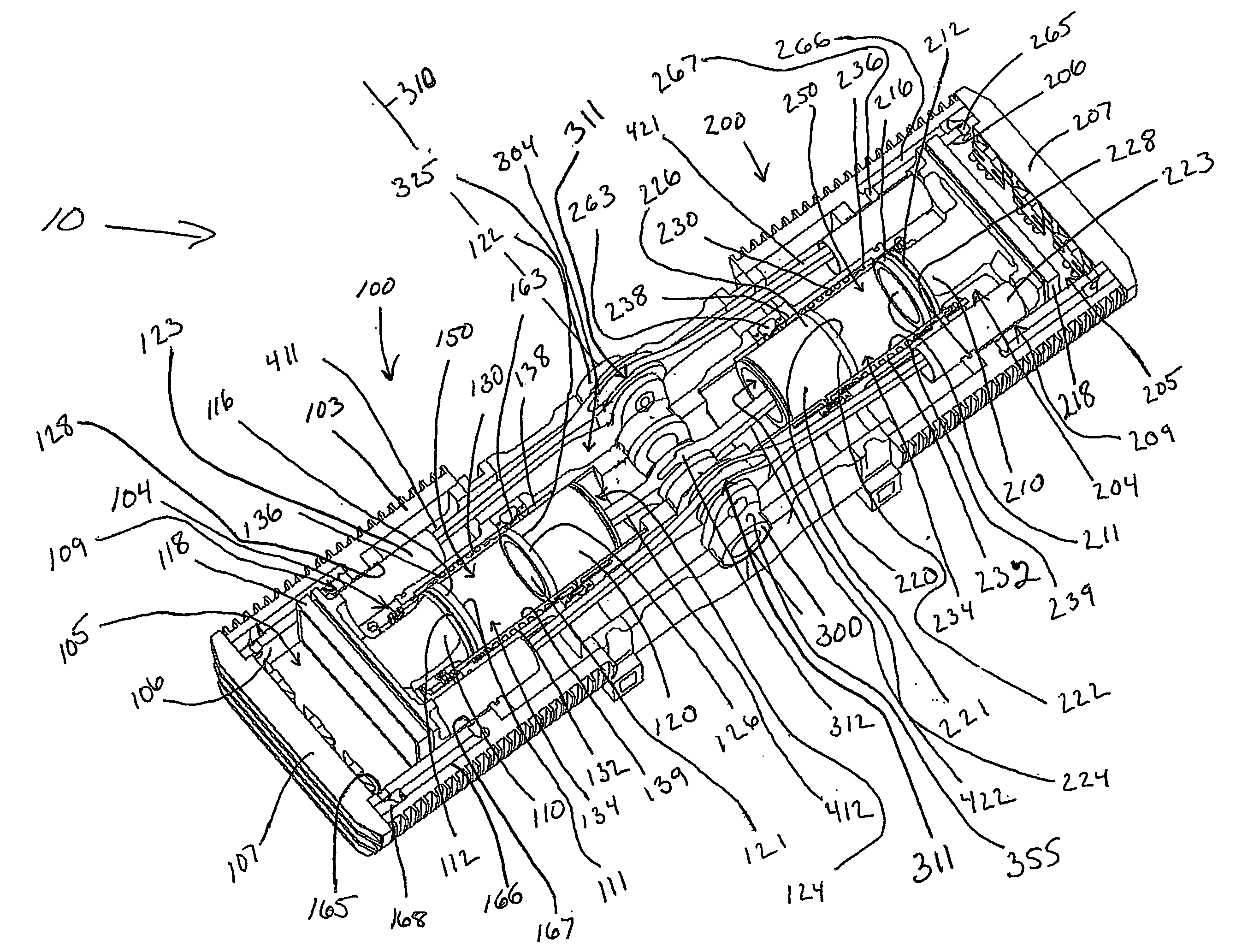
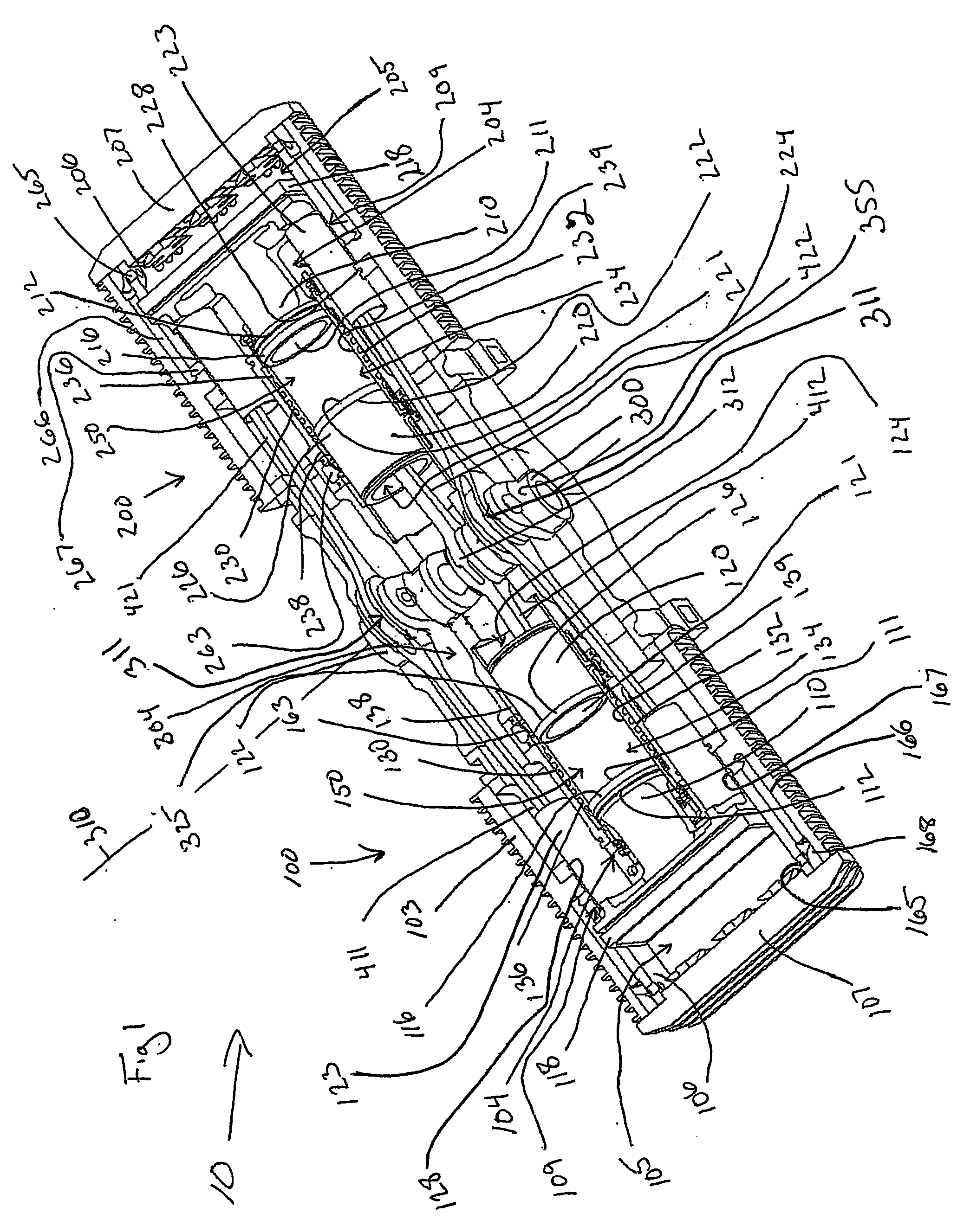
[0054]FIG. 1 is a partial cutaway isometric view of an engine 10 in accordance with an embodiment of the present invention. The engine 10 comprises a housing 103 containing a left cylinder 100, an axially aligned right cylinder 200 opposite the left cylinder 100, and a crankshaft 300 located there between. FIG. 1 depicts the engine 10 at a crankshaft angle of 0° or ...


PUM


Abstract

A two-stroke internal combustion engine is disclosed having opposed cylinders, each cylinder having a pair of opposed pistons, with all the pistons connected to a common central crankshaft. The inboard pistons of each cylinder are connected to the crankshaft with pushrods and the outboard pistons are connected to the crankshaft with pullrods. Each opposed cylinder further comprises an integrated scavenge pump for providing positive intake pressure. This configuration results in a compact engine with a very low profile, in which the free mass forces can be substantially balanced. The engine configuration also allows for asymmetrical timing of the intake and exhaust ports through angular positioning of the journals on the crankshaft.

Description

RELATED APPLICATION [0001] This application claims priority from U.S. Provisional Application Ser. No. 60 / 482,772, filed Jun. 25, 2003, and the contents of which are hereby incorporated by reference as if recited in full herein for all purposes.FIELD OF THE INVENTION [0002] The present invention relates generally to two-stroke internal combustion engines, and more specifically to a two-stroke internal combustion engine having a pair of opposed cylinders, each cylinder having a pair of opposed pistons. BACKGROUND OF THE INVENTION [0003] The design and production of internal combustion engines for the automotive and light aircraft industries are well-developed fields of technology. To be commercially viable, any new engine configuration must, without sacrificing performance, provide significant improvements in the areas of energy and raw material conservation (especially the improvement of fuel consumption), environmental protection and pollution control, passenger safety and comfort,...

Claims


Application Information

Patent Timeline
IPC IPC(8): F02B25/26F02B33/22F02B33/14F02B1/12F02B25/08F02B33/06F02B33/08F02B75/02F02B75/24F02B75/28
CPCF02B1/12F02B25/08F02B25/28F02B33/06F02B33/08F02B33/12F02B33/14F02B33/16F02B75/246F02B75/28F02B2075/025F02D13/028F01L7/04Y02T10/12
Inventor HOFBAUER, PETERTUSINEAN, ADRIAN
Owner ADVANCED PROPULSION TECH
Why Eureka
Try Eureka