Bragg fibers in systems for the generation of high peak power light

a technology of high-peak power light and bragg fibers, which is applied in the direction of electrical equipment, instrumentation, laser details, etc., can solve the problems of thermal damage to the surrounding non-irradiated regions, ultra-short pulses, and otherwise impossible or impractical to implement with other technologies, and achieve high dispersion of one type, high dispersion, and high dispersion

Inactive Publication Date: 2006-06-15
COHERENT INC
View PDF99 Cites 39 Cited by
  • Summary
  • Abstract
  • Description
  • Claims
  • Application Information

AI Technical Summary

Benefits of technology

[0029] Thus, Bragg-fiber waveguides can be used in a high-energy USP laser system, with the Bragg-fiber waveguides designed to have very high dispersion of one type to stretch pulses and very high dispersion of an opposite type to compress pulses. Using Bragg-fiber waveguides of high dispersion allows the optical signals to be stretched and compressed with relatively short lengths of Bragg-fiber waveguide, thus avoiding the necessity for the long lengths of traditional silica fiber or large optical gratings, allowing for extremely compact high-energy USP laser systems to be built.

Problems solved by technology

Numerous applications of ultrashort pulses have been developed that would be otherwise impossible or impractical to implement with other technologies.
Pulses with durations longer than about 10 psec can also ablate material if the pulse energy is greater than the ablation threshold, but thermal damage to the surrounding non-irradiated regions can occur.
However, there are some practical problems associated with commercializing applications of USP laser technology that have prevented USP technology from gaining mainstream acceptance.
Kerr effect nonlinearities, which include self-phase modulation, can cause pulse spectrum breakup, self focusing and catastrophic failure in the fiber.
One method of reducing the nonlinear effects in an optical fiber compressor is to increase the effective area of the propagating mode to decrease the peak power in the fiber, but this technique has been limited to producing pulses with a maximum energy of only a few μJ. FIG. 3a shows an example of pulse degradation due to nonlinearities in a standard large core silica fiber.
There is another problem with using a standard silica optical fiber to stretch the optical signal.
For this reason, commercial applications are generally only able to stretch a 1 psec pulse to about 200 psec, which does not allow for sufficient amplification for many applications.
In addition, the folding process requires difficult optical alignments.)
Compression is also a problem, and the greater the stretching, the more compression is required.
While optical gratings can also be used to compress optical signals, there are also limitations on the size of such gratings, thus limiting the amount of compression that can be achieved.
Thus, the size of the USP laser system rapidly becomes prohibitive for many applications compared to its performance.
For these reasons, in many cases commercial applications have been tabled due to the lack of practical USP laser sources.

Method used


Image

  • Bragg fibers in systems for the generation of high peak power light
  • Bragg fibers in systems for the generation of high peak power light
  • Bragg fibers in systems for the generation of high peak power light

Examples


Embodiment Construction

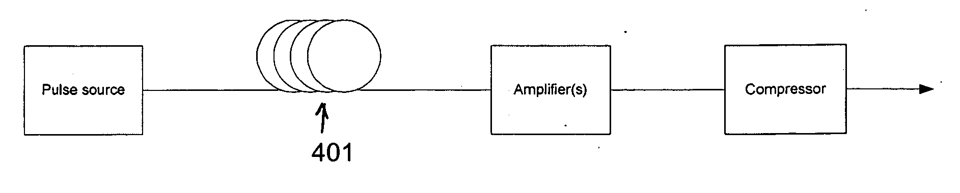
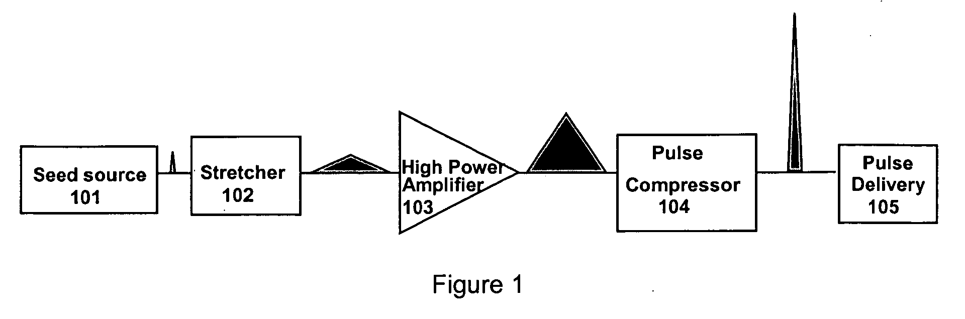
[0038] The present invention uses Bragg fibers of very high dispersion to accomplish stretching, amplification, and compression of an optical pulse in a relatively small length of fiber compared to the prior art. While optical fiber amplifier technology has improved dramatically in recent years and chirping with standard silica optical fiber is common, as discussed above practical compression within optical fibers has been an elusive goal. By reducing the amount of fiber required and propagating the signal primarily in a gaseous fiber core, the present invention allows for compact USP laser systems.

[0039] As mentioned earlier, the high peak power of a compressed high-energy pulse increases nonlinear optical effects in standard silica optical fiber, such as self-phase modulation and stimulated Raman scattering, distorting the pulse and generally preventing pulse re-compression. These optical nonlinearities can also cause pulse spectrum breakup, self focusing and catastrophic failure...


PUM


Abstract

The present invention generally concerns the use of Bragg optical fibers in chirped pulse amplification systems for the production of high-pulse-energy ultrashort optical pulses. A gas-core Bragg optical fiber waveguide can be advantageously used in such systems to stretch the duration of pulses so that they can be amplified, and/or Bragg fibers can be used to compress optical signals into much shorter duration pulses after they have been amplified. Bragg fibers can also function as near-zero-dispersion delay lines in amplifier sections.

Description

CROSS-REFERENCE TO RELATED APPLICATIONS [0001] The present application claims the benefit and priority of U.S. provisional patent applications Ser. No. 60 / 635,734, filed on Dec. 13, 2004, and entitled “Bragg Fibers For The Generation Of High Peak Power Light,” and 60 / 636,376, filed on Dec. 16, 2004, and entitled “Bragg Fibers In Systems For The Generation Of High Peak Power Light,” which are herein incorporated by reference.BACKGROUND OF THE INVENTION [0002] 1. Field of the Invention [0003] The present invention relates to producing high-energy ultrashort optical pulses, and, in particular, to the use of Bragg fibers for stretching or compressing these pulses in an ultrashort-pulse laser system. Bragg fibers may also be used in the delay lines of optical amplifiers and for the delivery of high peak power pulses of light. [0004] 2. Description of Related Art a. Ultrashort-pulse Laser Systems [0005] Ultrafast laser technology has been known and used for over 20 years. Chemists and ph...

Claims


Application Information

Patent Timeline
Patent Type & Authority Applications(United States)
IPC IPC(8): H01S3/13
CPCG02B6/02266G02B6/02304G02B6/02357G02B6/02361G02B6/02371H01S3/0057H01S3/08013H01S3/235
Inventor BRENNAN, JAMES F. IIIVAISSIE, LAURENTMIELKE, MICHAEL
Owner COHERENT INC
Why Eureka
Try Eureka