Steel pipe for an airbag system and a method for its manufacture
a technology of airbag system and steel pipe, which is applied in the direction of heat treatment apparatus, furniture, pedestrian/occupant safety arrangement, etc., can solve the problem that the steel pipe used as an accumulator for the high pressure inflating gas undergoes stress in an extremely short period of time, and achieves high toughness and high strength.
- Summary
- Abstract
- Description
- Claims
- Application Information
AI Technical Summary
Benefits of technology
Problems solved by technology
Method used
Image

Examples
example 1
[0063] Using steel billets having the chemical compositions shown in Table 1, a seamless steel pipe having nominal dimensions of an outer diameter of 70 mm and a wall thickness of 4.1 mm was manufactured from each billet by a hot working process which included heating the billet to 1250° C. and performing piercing and rolling by a conventional Mannesmann piercer-mandrel mill system. Each seamless steel pipe was then finished by cold drawing so as to have an outer diameter of 60.33 mm and a wall thickness of 3.35 mm. The pipe was then heated to 920° C. in a conventional walking beam furnace (heating rate: about 0.3° C. per second) with a temperature retention period of 10 minutes and then water quenched, after which it was tempered at a temperature which was no higher than the Ac1 transformation point of the steel by heating in a conventional walking beam furnace (atmosphere: air). In this manner, three seamless steel pipes for airbag systems having different tensile strengths were m...
example 2
[0069] Steel billets having the chemical compositions shown in Table 3 were each heated to 1250° C., after which each billet was pierced and hot rolled with a conventional Mannesmann piercer-mandrel mill system to obtain a seamless steel pipe with nominal dimensions of an outer diameter of 70 mm and a wall thickness of 4.1 mm. Each pipe was then subjected to cold drawing by a conventional method to provide the pipe with finished dimensions of an outer diameter of 60.33 mm and a wall thickness of 3.35 mm.
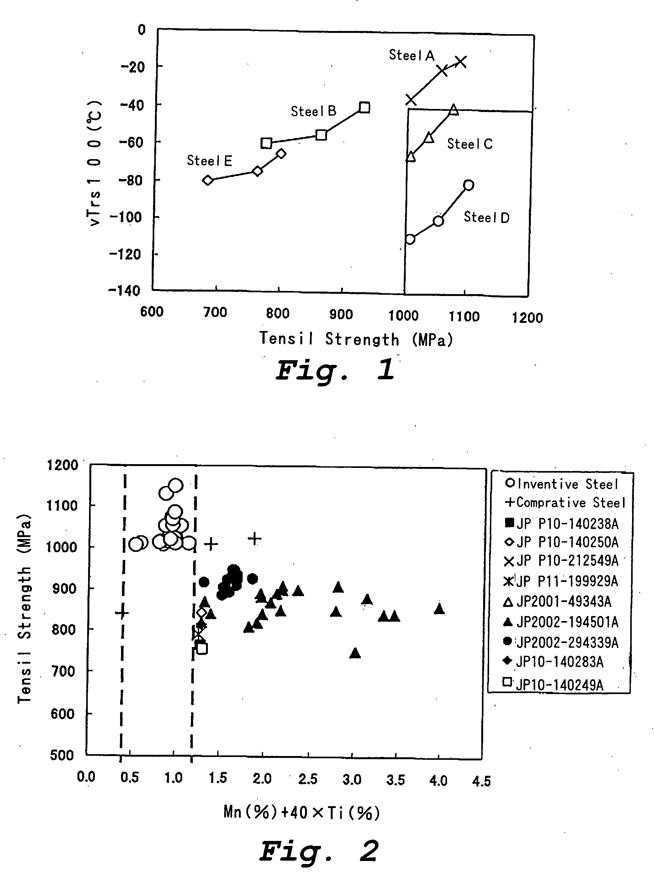
[0070] Steel Numbers 1-22 in Table 3 are steels for which the steel compositions satisfy the conditions prescribed by the present invention, and Steel Numbers 23-27 are comparative steels for which the contents of some elements do not satisfy the conditions prescribed for the present invention.
[0071] Each steel pipe which had been subjected to cold drawing was heated to 920° C. in a conventional walking beam furnace, and it was held in the furnace for 10 minutes and then water quen...
example 3
[0077] Seamless steel pipes having steel compositions shown in Table 3 were manufactured in the same manner as described in Example 2 except that the conditions for heat treatment were changed.
[0078] In this example, a steel pipe, which had been finished by piercing, hot rolling, and cold working as described in Example 2, was heated to 920° C. using a high frequency induction heating apparatus at a heat-up rate of about 20° C. / sec, and the induction heating was continued for 5 seconds after the temperature of the steel pipe reached 920° C. Thereafter, using the same procedure as in Example 2, the heated steel pipe was water quenched and tempered at a temperature of lower than the Ac1 transformation point of the steel for 30 minutes in a conventional walking beam furnace.
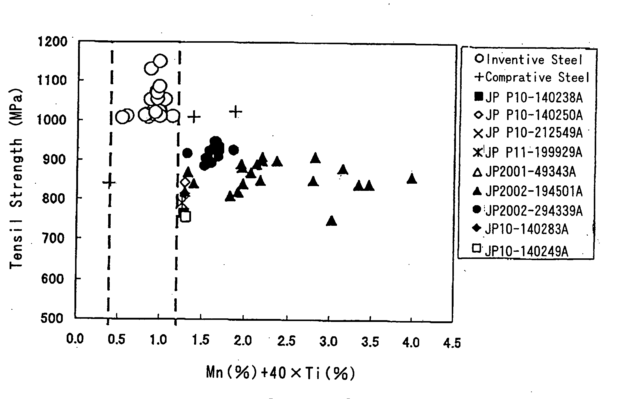
[0079] For each of the steel pipes, the γ grain size number of the steel was determined by the Bechet-Beaujard method according to JIS G0551. The tensile strength and vTrs100 of the steel pipe were determined in t...
PUM
| Property | Measurement | Unit |
|---|---|---|
| tensile strength | aaaaa | aaaaa |
| temperature | aaaaa | aaaaa |
| temperature | aaaaa | aaaaa |
Abstract
Description
Claims
Application Information
 - R&D
- Intellectual Property
- Life Sciences
- Materials
- Tech Scout
- Unparalleled Data Quality
- Higher Quality Content
- 60% Fewer Hallucinations
Browse by: Latest US Patents, China's latest patents, Technical Efficacy Thesaurus, Application Domain, Technology Topic, Popular Technical Reports.
© 2025 PatSnap. All rights reserved.Legal|Privacy policy|Modern Slavery Act Transparency Statement|Sitemap|About US| Contact US: help@patsnap.com