
Ink jet head and its manufacture method

a technology of jet head and manufacturing method, which is applied in the direction of liquid surface applicators, coatings, printing, etc., can solve the problems of liquid repellent layer peeling, material itself not having the liquid repellent nature, and materials that cannot form solid structures like nozzles, etc., to achieve good patterning characteristic, improve the compatibility of liquid repellent material and photo resist composition, and high precision structure

Inactive Publication Date: 2006-06-22
CANON KK
View PDF16 Cites 43 Cited by
  • Summary
  • Abstract
  • Description
  • Claims
  • Application Information

AI Technical Summary

Benefits of technology

This patent is about a new ink jet head and a method of manufacturing it that has high liquid repellency, durability against wiping, and ease of wiping simultaneously. The invention uses a liquid repellent material made of a hydrolysable silane compound and a photo-polymerizable resin composition that improves the accuracy of the nozzle and simplifies the manufacturing process. The nozzle material has high liquid repellency and durability against wiping without the need for additional liquid repellent processing. The invention improves the performance of the ink jet head and allows for high-quality image recording.

Problems solved by technology

Moreover, when the liquid repellent layer is prepared on the surface, the liquid repellent layer needs to adhere to its lower layer, and the problem of peeling off of liquid repellent layer may occur.
However, most of them were just the surface treatment of the formed nozzle, and the nozzle material itself did not have the liquid repellent nature.
However, these surface treatments were aimed at liquid repellent nature grant, and were not those in which the liquid repellent material itself has patterning nature.
These materials could not form the solid structure like a nozzle.
However, since fluorine-containing compounds generally have low dissolubility to other resin, it was difficult to mix with photosensitive resin and to use together.
Although the block copolymer having fluorine-containing group was indicated in Japanese Patent Application Laid-Open No. 2002-105152 as a coating composition, it could not be applied to the high-precision patterning like nozzle forming.

Method used


Image

  • Ink jet head and its manufacture method
  • Ink jet head and its manufacture method
  • Ink jet head and its manufacture method

Examples


embodiment 1

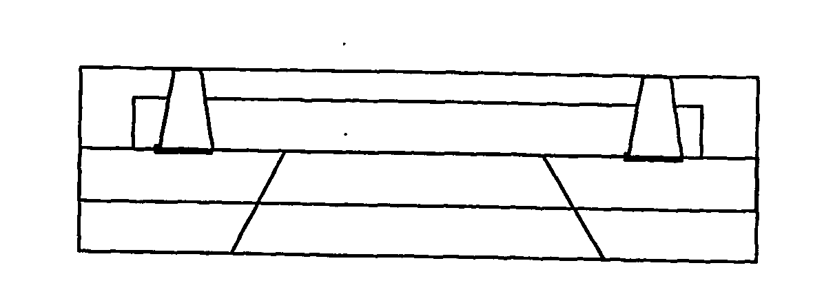
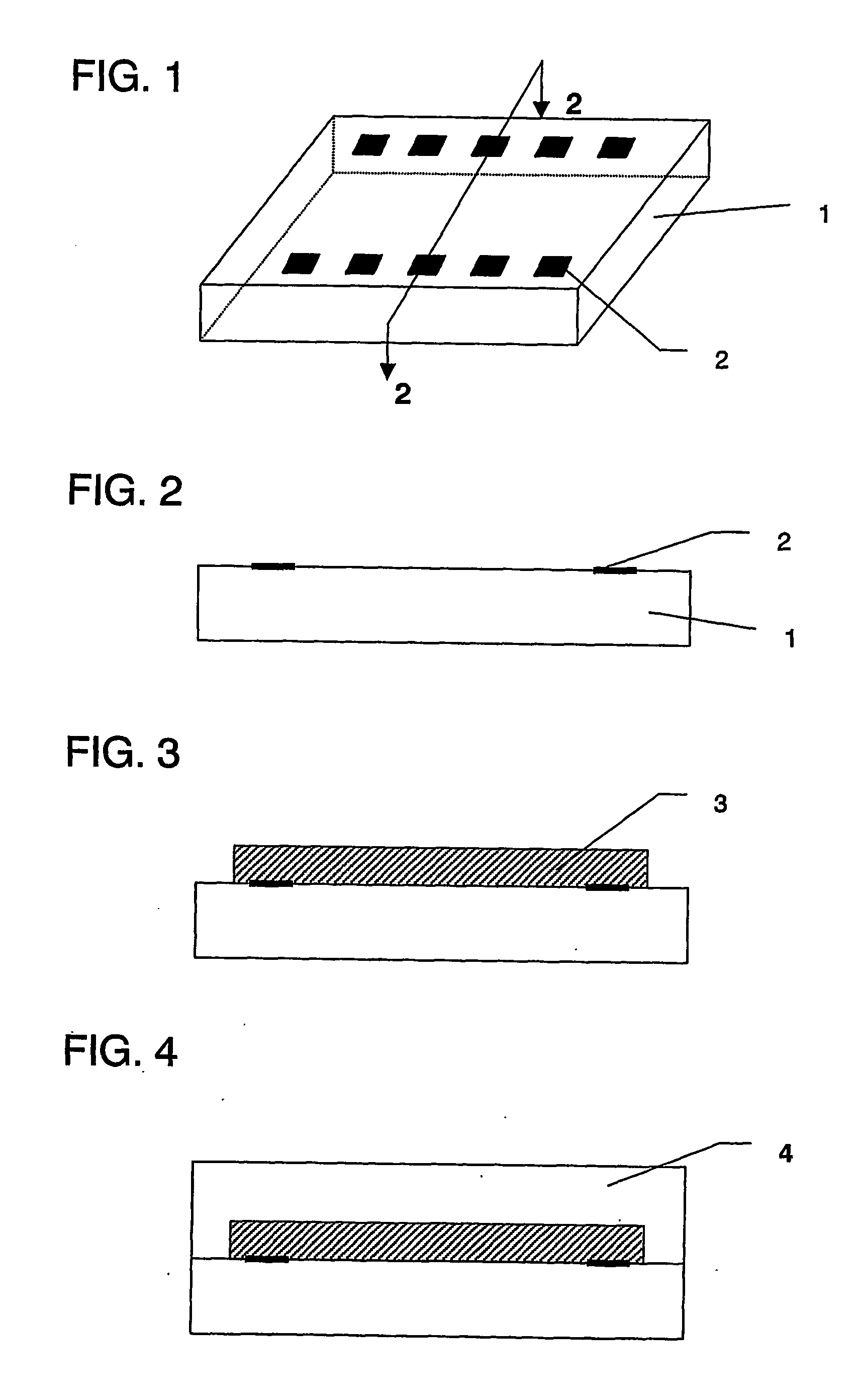
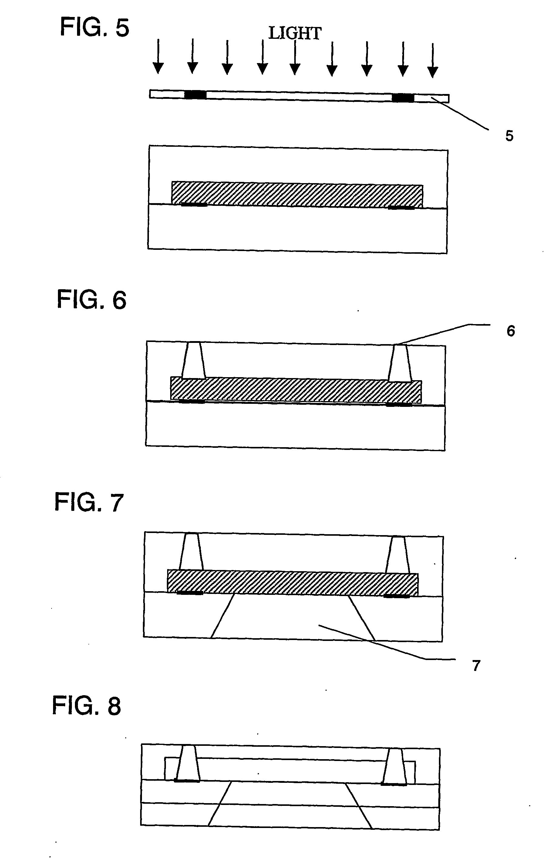
[0092] An ink jet head was produced according to the procedure shown in the above-mentioned method in FIGS. 1 to 8.

[0093] At first, the silicone substrate 1 having the electric heat conversion element as ink ejection pressure generating element 2 was prepared, and the dissoluble resin layer was formed by applying polymethyl isopropenyl ketone (ODUR-1010, Tokyo Oka Kogyo Kabushiki Kaisha) by spin coating on the silicone substrate. Subsequently, after prebaking at 120° C. for 6 minutes, pattern exposure of ink passage was performed by mask aligner UX3000 (USHIO Electrical Machinery).

[0094] Exposure time was for 3 minutes, and development was carried out with methyl isobutyl ketone / xylene= 2 / 1, and rinsed with xylene.

[0095] Said polymethyl isopropeny ketone is the so-called positive type resist, which decomposes and becomes soluble to the organic solvent by UV irradiation. The pattern formed with the dissoluble resin material was the portion which was not exposed in the case of patt...

embodiment 2

[0098] An ink jet head was produced like embodiment 1 except for applying composition 2 shown in Table 2 instead of the composition 1 as underlayer, which application and prebaking were repeated twice, and as the most upper layer above-mentioned composition 1 was applied.

TABLE 2Composition 2Epoxy resinEHPE-3150, Daicel Chemical100partsAdditive1,4-HFAB, Central Glass20partsphoto cationicSP172, Asahi Denka Industry5partsinitiatorReducing agentcopper (II) trifluoromethanesulfonate0.5partsSilane couplingA187, Nippon Unicar5partsagent

1,4-HFAB: (1,4-bis(2-hydroxyhexafluoroisopropyl)benzene)

embodiment 3

[0099] An ink jet head was made like embodiments, except for using the composition 3 shown in Table 3 instead of the composition 1.

TABLE 3Composition 3hydrolysablehydrolysable condensation5partscondensationproduct of synthetic exampleproduct1 (20 wt %)Epoxy resinEHPE-3150, Daicel Chemical100partsAdditive1,4-HFAB, Central Glass20partsphoto cationicSP172, Asahi Denka Industry5partsinitiatorSilane couplingA187, Nippon Unicar5partsagent

1,4-HFAB: (1,4-bis(2-hydroxyhexafluoroisopropyl)benzene)


PUM

PropertyMeasurementUnit
surface roughness Raaaaaaaaaaa
melting pointaaaaaaaaaa
Raaaaaaaaaaa

Abstract

An ink jet head is formed of a nozzle material compound of a condensation product comprising a hydrolysable silane compound having a fluorine-containing group and a photo-polymerizable resin composition.

Description

TECHNICAL FIELD [0001] This invention is in an ink jet head and its manufacture method. BACKGROUND ART [0002] Recently, the technical development to the improvement in a performance of smaller droplet, higher drive frequency and more number of nozzle is continued in order to make the record characteristic more advanced in an ink jet record system. And image recording is performed by ejecting liquid from an ejection opening as small droplet which adheres to the recording medium typified by paper. [0003] Here, a surface treatment is becoming more important to maintain ejecting performance by keeping ejecting opening surface as same condition at any time. Moreover, it is common to wipe off the ink which remained on the surface by e.g. rubber blade periodically to maintain the condition of the ejecting opening surface in an ink jet head. A liquid repellent material is demanded for easy wiping, and wiping durability. [0004] Moreover, when the liquid repellent layer is prepared on the sur...

Claims


Application Information

Patent Timeline
Patent Type & Authority Applications(United States)
IPC IPC(8): B41J2/16B41J2/14
CPCB41J2/1433B41J2/1603B41J2/1606Y10T29/49401B41J2/1631B41J2/1639B41J2/1645B41J2/162
Inventor HINO, ETSUKOOHKUMA, NORIOSCHMITDT, HELMUTBECKER-WILLINGER, CARSTENKALMES, PAMELE
Owner CANON KK
Learn More