Micromechanical and related lidar apparatus and method, and fast light-routing components

a lidar and micromechanical technology, applied in the direction of reradiation, distance measurement, instruments, etc., can solve the problems of operational inconvenience and expense, the switching speed is not optimal, and the switching technique too is relatively slow, so as to achieve a wide visual field, reduce the effect of weight, and reduce the power of the apparatus

Active Publication Date: 2006-06-22
ARETE ASSOCIATES INC
View PDF5 Cites 170 Cited by
  • Summary
  • Abstract
  • Description
  • Claims
  • Application Information

AI Technical Summary

Benefits of technology

[0112] In particular, such a scanning capability that is basically within the optical system enables turning of an exploratory light beam to characterize a very broad visual field, far more quickly and with far smaller, lighter and less

Problems solved by technology

Though faster than electrolysis, thermal effects operate on the order of milliseconds and accordingly are far from optimal in switching speed.
Pohl teaches tunneling of light through liquid metal, for pathlengths on the order of a fractional wavelength; while possibly useful for kilohertz CW modulation, this technique too is relatively slow for switching.
Many or most lidar and related imaging systems are bulky and heavy, and require relatively high operating power—leading to operational inconvenience and expense.
Curiously enough, one reason for these undesirable characteristics is the bulk and weight associated with apertures used in transmitting and then receiving optical signals.
Although philosophically speaking an aperture is in essence no more than a hole, in actual practice the hardware (including lenses and the like when prese

Method used


Image

  • Micromechanical and related lidar apparatus and method, and fast light-routing components
  • Micromechanical and related lidar apparatus and method, and fast light-routing components
  • Micromechanical and related lidar apparatus and method, and fast light-routing components

Examples


Embodiment Construction

Applications

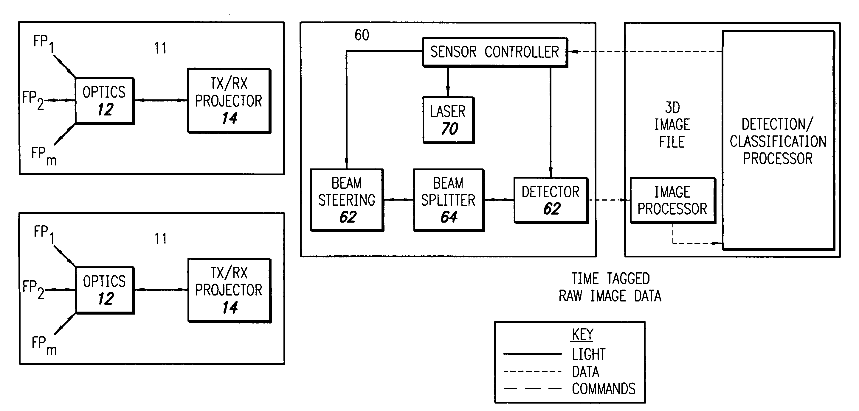
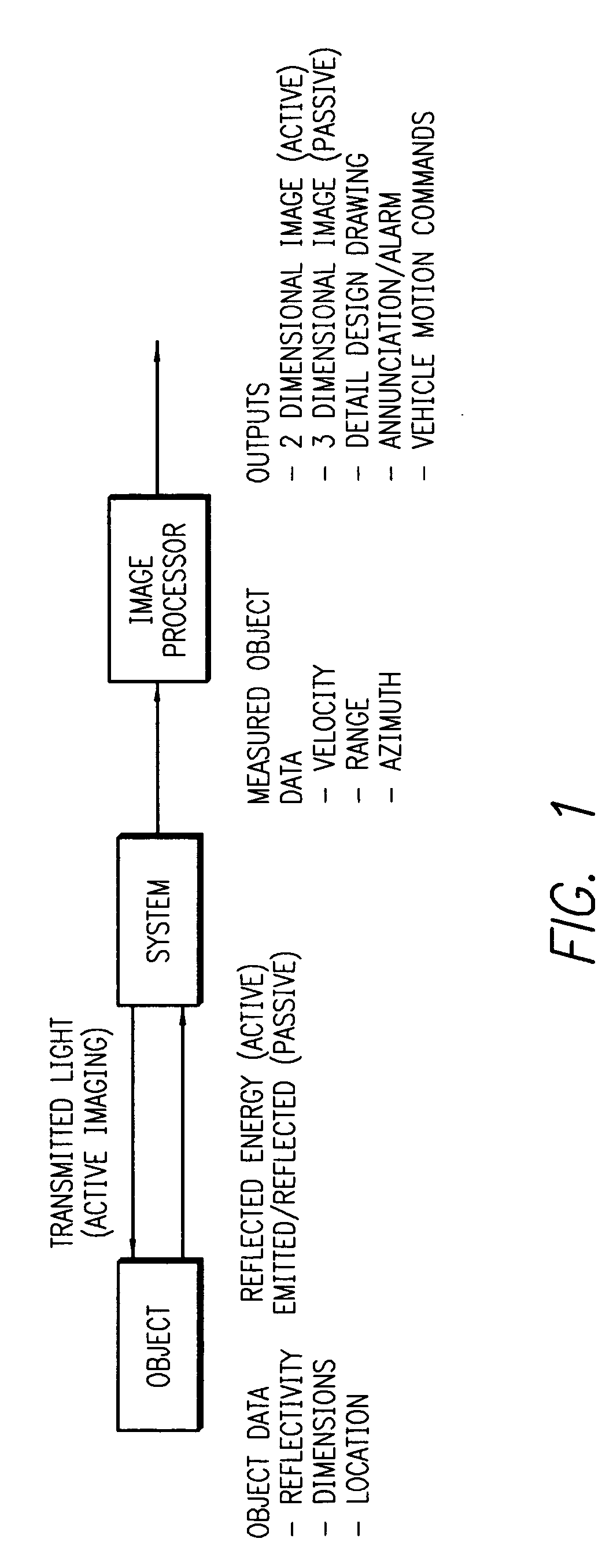
[0157] In particularly preferred applications and embodiments, the invention is used as an optical system, or as part of an optical system, for detection and ranging as well as imaging (FIG. 1). The imaging applications can be active or passive depending on the result desired.

[0158] In active imaging, a source is used to illuminate an object of interest. Passive imaging instead collects illumination emitted from the object, or reflected from the environment, to form an image of an object of interest.

[0159] These imaging applications are applied to many fields including but not limited to industrial automation, aerospace, industrial inspection, intelligence, and reverse engineering (i. e. regeneration of detailed engineering designs from already-built hardware) as well as guidance and control (FIG. 1). The last-mentioned field includes applications such as collision avoidance, object interception and vehicle rendezvous. In these applications, measured values for locat...


PUM


Abstract

Several systems and a method are taught for rapid modulation of a light beam in lidar and other imaging. Most of these involve micromechanical and other very small control components. One such unit is a light-switching fabric, based on displacement of liquid in a tube that crosses a junction of two optical waveguides. In some forms, the fabric is preferably flexible to enable folding or coiling to form a two-dimensional face that interacts with optical-fiber ends an opposed fiber bundle. The rapid operation of the switch fabric enables it to be used as a beam-splitter, separating incoming and return beams; and also to form pulses from supplied CW light. Other control components include micromechanical mirrors (e. g. MEMS mirrors) operated in arrays or singly, liquid-crystal devices, and other controlled-birefringence cells. Some of these devices are placed within an optical system for directional light-beam steering.

Description

[0001] This document claims priority of U.S. provisional patent application Ser. No. 60 / 381,286, filed May 17, 2002, and International patent application PCT / US03 / 16062—both wholly incorporated by reference into this document. OTHER RELATED DOCUMENTS [0002] Closely related documents are other, coowned U.S. utility-patent documents and references—also incorporated by reference. Those documents are in the names of: [0003] Bowker et al., application Ser. No. 09 / 125,259, “CONFOCAL-REFLECTION STREAK LIDAR APPARATUS WITH STRIP-SHAPED PHOTOCATHODE, FOR APPLICATIONS AT A WIDE RANGE OF SCALES”; [0004] Lubard et al., application Ser. No. 09 / 390,487, “LIDAR WITH STREAK-TUBE IMAGING, INCLUDING HAZARD DETECTION IN MARINE APPLICATIONS; RELATED OPTICS”; [0005] Kane et al., application Ser. No. 10 / 142,654 “HIGH-SPEED, LOW—POWER OPTICAL MODULATION APPARATUS AND METHOD”; [0006] Gleckler, application Ser. No. 10 / 258,917—published Nov. 1, 2001 as WO 01 / 81949, “VERY FAST TIME RESOLVED IMAGING IN MULTIPA...

Claims


Application Information

Patent Timeline
IPC IPC(8): G01C3/08
CPCG01S7/4817G01S7/4818G01S17/42G02B6/3512G02B6/3538G02B6/3556G02B6/3584G02B6/3588G02B6/4204
Inventor KANE, DAVID M.
Owner ARETE ASSOCIATES INC
Why Eureka
Try Eureka