Deposition of LiCoO2

a technology of licoo2 and film, applied in the direction of cell components, flat cell grouping, sustainable manufacturing/processing, etc., can solve the problems of reducing the yield of such batteries, limiting the choice of substrate materials, and increasing costs, and achieves high deposition rate and high rate

Active Publication Date: 2006-06-22
DEMARAY
View PDF99 Cites 80 Cited by
  • Summary
  • Abstract
  • Description
  • Claims
  • Application Information

AI Technical Summary

Benefits of technology

[0013] In accordance with the present invention, deposition of LiCoO2 layers in a pulsed-dc physical vapor deposition process is presented. Such a deposition can provide a low-temperature, high deposition rate deposition of a crystalline layer of LiCoO2 with a desired <101> orientation. Some embodiments of the deposition address the need for high rate deposition of LiCoO2 films, which can be utilized as the cathode layer in a solid state rechargeable Li battery. Embodiments of the process according to the present invention can eliminate the high temperature (>700° C.) anneal step that is conventionally needed to crystallize the LiCoO2 layer.

Problems solved by technology

Such a high temperature anneal, however, severely limits the materials that can be utilized as the substrate, induces destructive reaction with the lithium containing cathode material and often requires the use of expensive noble metals such as gold.
Such high thermal budget processes (i.e., high temperatures for extended periods of time) are incompatible with semiconductor or MEM device processing and limit the choice of substrate materials, increase the cost, and decrease the yield of such batteries.
It is very difficult to form a uniform deposition either by sputtering a material layer or by bombardment with an ion flux.
Utilization of two uniform simultaneous distributions from two sources that do not occupy the same position and extent with respect to the substrate enormously increases the difficulties involved in achieving a uniform material deposition.
These references do not disclose a uniform materials deposition, which is required for reliable production of thin-film batteries.
It is even more difficult to scale a substrate to manufacturing scale, such as 200 mm or 300 mm.
Further, conventional materials and production processes can limit the energy density capacity of the batteries produced, causing a need for more batteries occupying more volume.

Method used


Image

  • Deposition of LiCoO2
  • Deposition of LiCoO2
  • Deposition of LiCoO2

Examples


Embodiment Construction

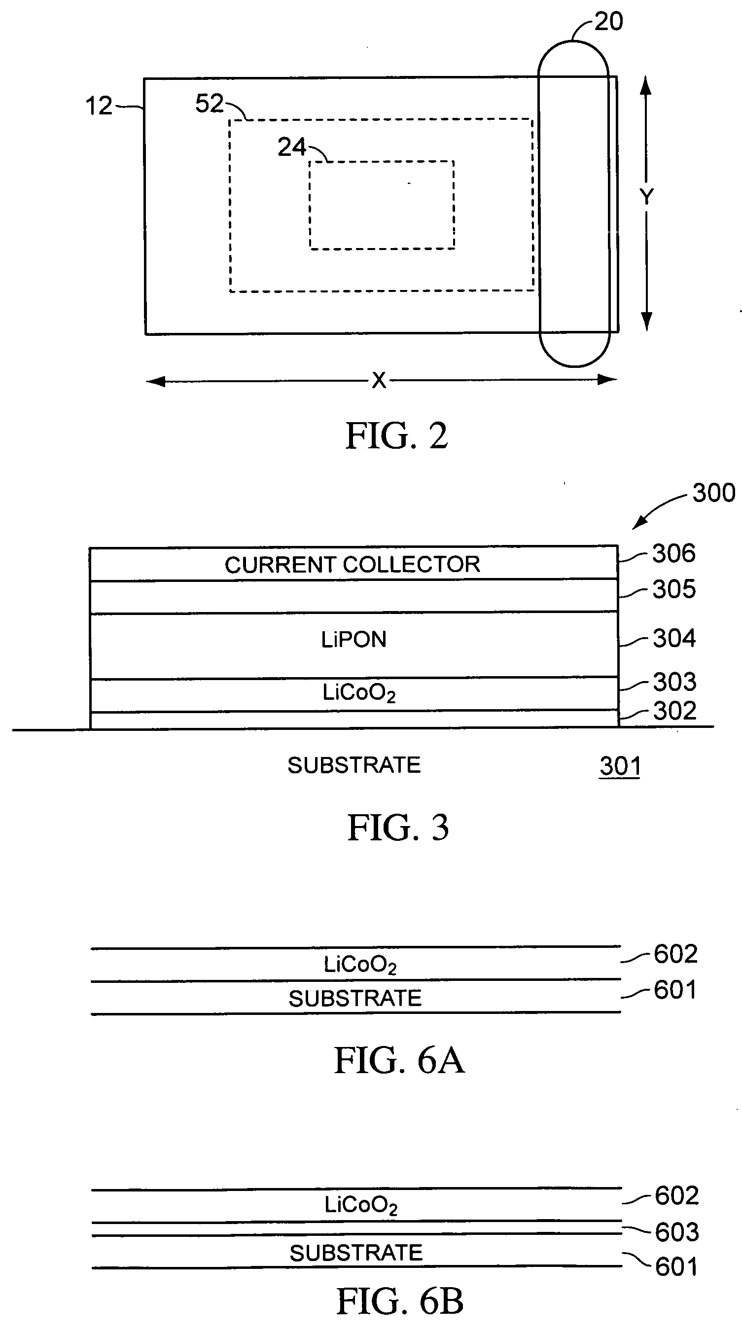
[0039] In accordance with embodiments of the present invention, LiCoO2 films are deposited on a substrate by a pulsed-dc physical vapor deposition (PVD) process. In contrast to, for example, Kim et al., LiCoO2 films according to some embodiments of the present invention provide a crystalline LiCoO2 film as deposited on a substrate at a substrate temperature as low as about 220° C. during deposition, without the use of a metallic nucleation or barrier underlying film. The as-deposited crystalline LiCoO2 films can be easily ripened to very high crystalline condition by anneal at about 700° C. for as little as 5 minutes without the use of an underlying precious metal film. In addition, the as deposited crystalline films, when positioned on a noble metal film can be annealed at much further reduced temperatures, for example as low as 400 to 500° C., providing for deposition, annealing, and production of solid state batteries on lower temperature substrates.

[0040] In the present applica...


PUM

PropertyMeasurementUnit
temperatureaaaaaaaaaa
resistanceaaaaaaaaaa
temperatureaaaaaaaaaa

Abstract

In accordance with the present invention, deposition of LiCoO2 layers in a pulsed-dc physical vapor deposition process is presented. Such a deposition can provide a low-temperature, high deposition rate deposition of a crystalline layer of LiCoO2 with a desired <101> or <003> orientation. Some embodiments of the deposition addresses the need for high rate deposition of LiCoO2 films, which can be utilized as the cathode layer in a solid state rechargeable Li battery. Embodiments of the process according to the present invention can eliminate the high temperature (>700° C.) anneal step that is conventionally needed to crystallize the LiCoO2 layer. Some embodiments of the process can improve a battery utilizing the LiCoO2 layer by utilizing a rapid thermal anneal process with short ramp rates.

Description

RELATED APPLICATION [0001] The present application claims priority to Provisional Application No. 60 / 651,363, filed on Feb. 8, 2005, by Hongmei Zhang and Richard E. Demaray, and to Provisional Application No. 60 / 634,818, filed on Dec. 8, 2004, by the same inventors, each of which are herein incorporated by reference in their entirety.BACKGROUND [0002] 1. Field of the Invention [0003] The present invention is related to thin-film solid-state batteries and, in particular, the deposition of LiCoO2 films and layers for battery manufacture. [0004] 2. Discussion of Related Art [0005] Solid-state thin-film batteries are typically formed by stacking thin films on a substrate in such a way that the films cooperate to generate a voltage. The thin films typically include current collectors, a cathode, an anode, and an electrolyte. The thin films can be deposited utilizing a number of deposition processes, including sputtering and electroplating. Substrates suitable for this application have co...

Claims


Application Information

Patent Timeline
Patent Type & Authority Applications(United States)
IPC IPC(8): H01M4/52B05D5/12H01M10/38C23C14/34H01M4/02H01M4/04H01M4/131H01M4/1391H01M4/525H01M10/052H01M10/0562H01M10/0585H01M10/36
CPCC23C14/08Y10T29/49115C23C14/5806H01M4/0423H01M4/0426H01M4/0428H01M4/0471H01M4/131H01M4/1391H01M4/525H01M4/66H01M4/661H01M4/667H01M6/185H01M6/188H01M6/46H01M10/052H01M10/0562H01M10/0585H01M2004/028H01M2300/002H01M2300/0071Y02E60/122C23C14/35Y02E60/10Y02P70/50C23C14/34
Inventor ZHANG, HONGMEIDEMARAY, RICHARD E.SHAO, MAY
Owner DEMARAY
Why Eureka
Try Eureka