High strength, high toughness, high carbon steel wire rod and method of production of same

a high-toughness, high-carbon steel technology, applied in the direction of manufacturing tools, furnaces, heat treatment equipment, etc., can solve the problems of poor toughness/ductility of wire after drawing, drop in productivity or yield, poor toughness after wire drawing, etc., to achieve high strength, high toughness, high strength

Inactive Publication Date: 2006-06-29
NIPPON STEEL CORP
View PDF2 Cites 19 Cited by
  • Summary
  • Abstract
  • Description
  • Claims
  • Application Information

AI Technical Summary

Benefits of technology

[0015] (1) A high strength and high toughness carbon steel wire rod containing high C content of C in an amount of 0.95 wt % or less, characterized by further containing, Zr in an amount of 10 wt ppm or more and 500 wt ppm or less and by including in said wire rod inclusions having a size of 0.1 to 10 μm, having a mole fraction of Zr of 0.2 or more in the ZrO2 inclusions, and having a numerical density of 500 to 3000 / mm2.
[0016] (2) A high strength and high toughness carbon steel wire rod as set forth in (1), characterized in that said wire rod has a 90% or more pearlite structure and an average value of the proeutectoid cementite area ratio of 5% or less in a center region of less than 20% of the wire rod radius from the center of said wire rod.
[0017] (3) A high strength and high toughness carbon steel wire rod as set forth in (1), characterized in that said wire rod has a 90% or more pearlite structure and a size (maximum length) of the micromartensite grains of 100 μm or less in a center region of less than 20% of the wire rod radius from the center of said wire rod.

Problems solved by technology

However, if the increase in the amount of C causes the steel material to become a hyper-eutectoid composition, at the time of rolling or patenting, when cooling from the austenite region, proeutectoid cementite tends to precipitate in a network at the austenite grain boundaries.
As a result, the frequency of breakage at the time of wire drawing also becomes high, thereby inviting a drop in productivity or yield and resulting in poor toughness / ductility of the wire after drawing.
In high carbon wire rod, C and Mn concentrate at the center segregation part, so proeutectoid cementite is formed at the austenite grain boundaries, micromartensite is produced, breakage is caused at the time of wire drawing, or the toughness after wire drawing becomes poor.
However, if performing electromagnetic stirring in the mold, the continuous casting powder becomes entrained and causes defects.
For example, with high carbon wire rod, this sometimes becomes a cause of breakage at the time of wire drawing.
Therefore, there is a limit to raising the thrust of the electromagnetic stirring in the mold.
Further, equiaxed crystals obtained by electromagnetic stirring are relatively large equiaxed crystals, so there is the problem that the segregated grains at the center segregation (size of parts where the solute becomes remarkably concentrated near the center of the bloom or billet) do not become sufficiently fine.
In the above way, sufficient reduction of center segregation in continuous casting is an important technical issue even at the present.

Method used


Image

  • High strength, high toughness, high carbon steel wire rod and method of production of same
  • High strength, high toughness, high carbon steel wire rod and method of production of same
  • High strength, high toughness, high carbon steel wire rod and method of production of same

Examples


example 1

[0065] Next, examples will be given to explain the present invention more specifically.

[0066] The high carbon steel wire rod of each of the chemical compositions shown in Table 1 was hot rolled after continuous casting to obtain steel wire rod of a diameter of 11 mm, then was directly patented or reheated and then patented under various conditions. (Lead patenting conditions: reheating at 950° C.×5 min→isothermal transformation 540° C.×4 min).

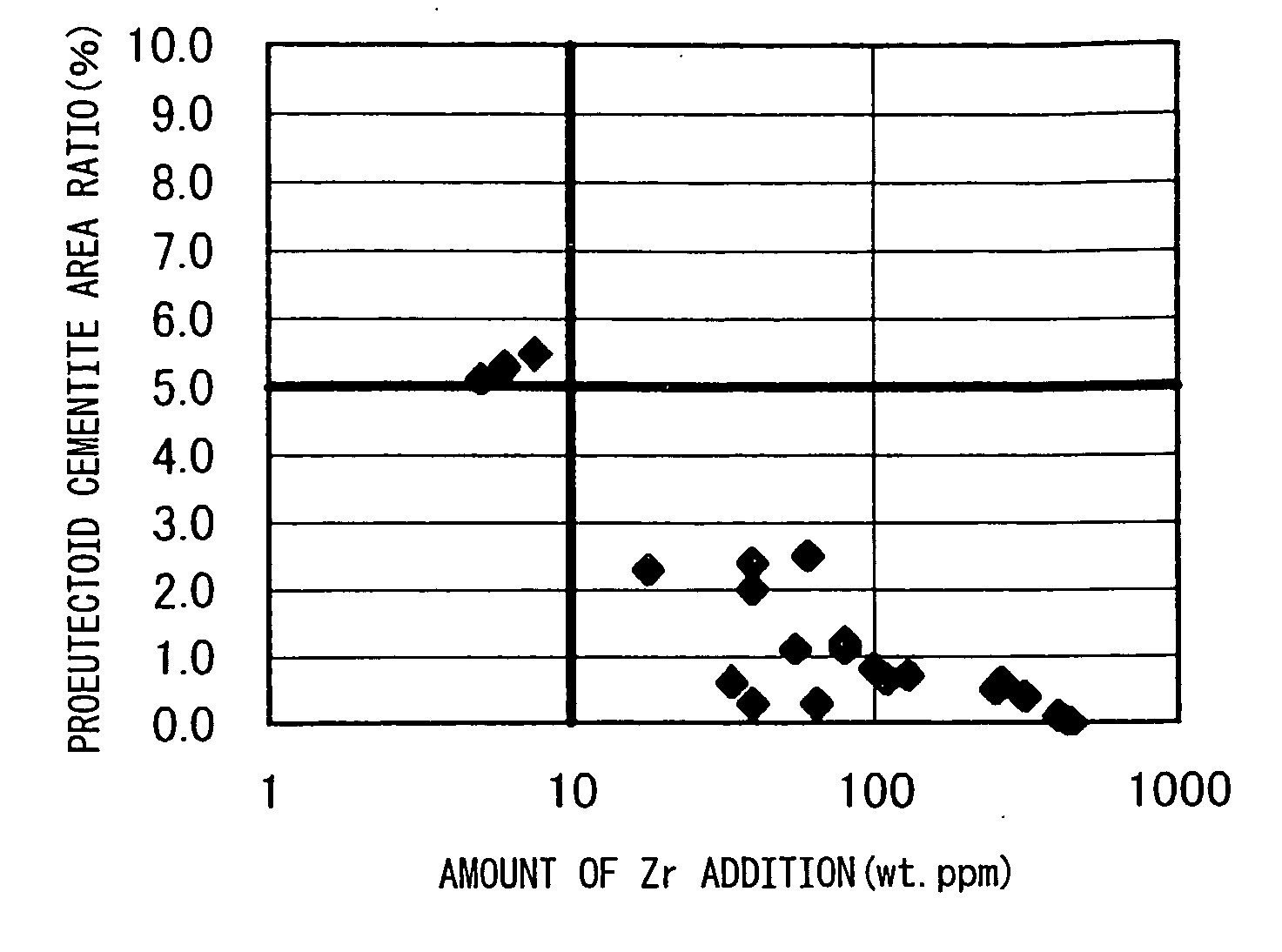
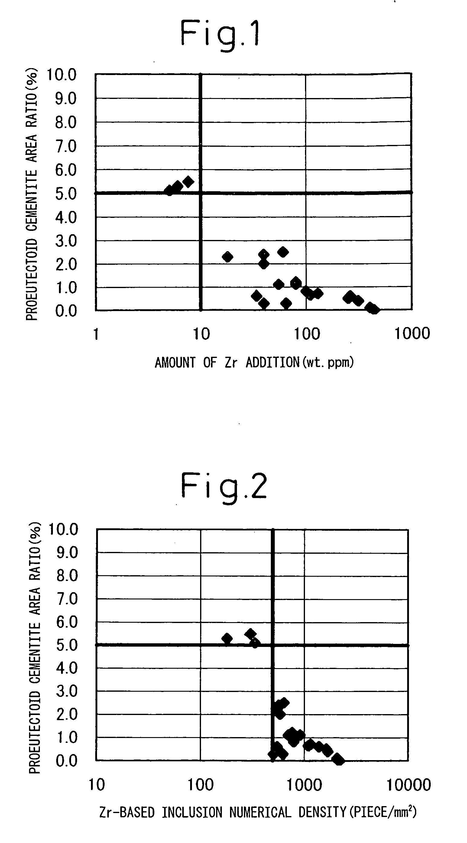
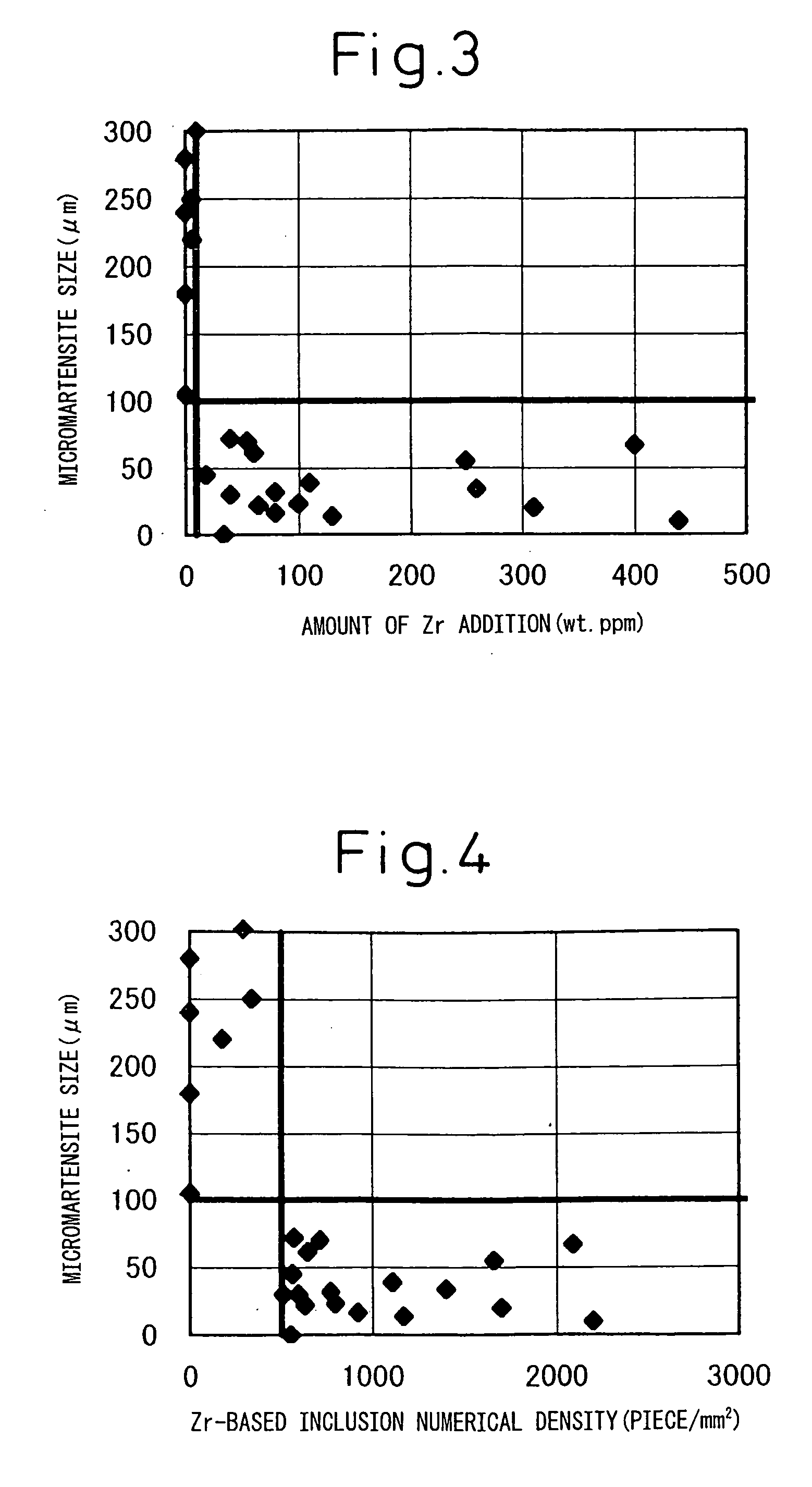
[0067] This patenting material was polished by embedded abrasives and chemically corroded by dodecyl sulfonic acid. It was then observed under an SEM to determine the proeutectoid cementite area ratio in the center region (r<0.2 d) of a length (r) from the center (p) of less than 20% of the wire rod radius (d). Further, the material was polished by embedded abrasives and chemically corroded using a Nytal solution and then observed under an SEM to determine the size of the micromartensite grains at the C section. Further, the inventors used TE...

example 2

[0071] Molten steel containing C:0.80%, Si:0.20%, Mn:0.70%, P:0.010%, and S:0.01% was melted in a converter, added with Ti or Al, then added with Zr in the ladle.

[0072] This molten steel was cast by a bloom continuous casting machine. An electromagnetic stirring is performed in the mold. Further, depending on the case, at the end of the solidification, rolling reduction was applied by the light reduction method. The size of the bloom was 300 mm×500 mm. The bloom was cut and evaluated by the above methods for the solidified structure, center segregation, and inclusions. (After casting, the bloom was rolled to a wire rod which was then measured for the area ratio of the proeutectoid cementite.)

[0073] In Table 3, Comparative Steel No. 8 shows a bloom obtained without addition of Zr. Almost no equiaxed crystals were formed. Even if formed, the equiaxed crystals were extremely coarse and the aggregate grain size was also large. As opposed to this, in Invention Steel Nos. 19 to 21 each ...


PUM

PropertyMeasurementUnit
sizeaaaaaaaaaa
sizeaaaaaaaaaa
diameteraaaaaaaaaa

Abstract

The present invention provides a high strength, high toughness steel wire rod useful for a PC steel wire, galvanized steel strands, spring use steel wire, cables for suspension bridges, etc. By hot rolling, then directly patenting or reaustenitizing, then patenting a high carbon steel wire rod of a specific chemical composition of the steel and chemical composition, size, and numerical density of inclusions, piano wire rod or high carbon steel wire rod having a structure of mainly pearlite, having an average value of the proeutectoid cementite area ratio of 5% or less in a center region of less than 20% of the wire rod diameter from the center of the wire rod, having a micromartensite size of the C section of 100 μm or less, having a tensile strength of the 170 kgf/mm2 class or more, and having a drawing ratio at break of 30% or more is obtained.

Description

TECHNICAL FIELD [0001] The present invention relates to piano wire rod or high carbon steel wire rod used for PC steel wire, galvanized steel strands, spring use steel wire, cables for suspension bridges, etc. Further, the present invention relates to a method of production for obtaining a bloom or billet with less center segregation or porosity and therefore a good internal quality in the process of casting molten steel. BACKGROUND ART [0002] In producing high carbon steel wire, the normal practice is to patent and draw a hot rolled wire rod one or more times to finish it to a predetermined wire diameter. This high carbon steel wire has to be ensured a predetermined strength and be ensured a performance sufficient even for the toughness / ductility evaluated by the drawing ratio at break etc. [0003] The fact that for increasing the strength of high carbon steel wire, increasing the amount of C in chemical compositions of the steel is the most economical and effective means has been c...

Claims


Application Information

Patent Timeline
Patent Type & Authority Applications(United States)
IPC IPC(8): C22C38/14C21D9/52C22C38/00C22C38/02C22C38/04C22C38/52C23C2/02
CPCC22C38/02C22C38/04C22C38/14C23C2/02C23C2/0224
Inventor YAMASAKI, SHINGONISHIDA, SEIKIKAJITANI, TOSHIYUKIYAMADA, WATARUNISHIKAWA, YOSHITAKAMUROGA, NARIYASUKOMIYA, NOBUYUKI
Owner NIPPON STEEL CORP
Why Eureka
Try Eureka