Method and device for the secondary treatment and the cooling of preforms

a technology for secondary treatment and preforms, applied in the field of secondary treatment and preform cooling, can solve the problems of reducing the productivity of the entire system, requiring precision, and requiring extensive water cooling

Inactive Publication Date: 2006-06-29
NETABTAL MASCHEN
View PDF8 Cites 52 Cited by
  • Summary
  • Abstract
  • Description
  • Claims
  • Application Information

AI Technical Summary

Benefits of technology

[0013] The new invention proceeds primarily from the cooling concept where the individual preforms are introduced into the cooling sleeves only with the blow-moulded part during the secondary cooling. In doing so, the threaded parts project past the cooling sleeves. This has the enormous advantage that the preforms are inserted into and removed from the cooling sleeves of the removal device in a linear movement. The new solution proposes an optimal contact with the cooling sleeve in particular in the phase of intensive cooling immediately following the removal from the casting moulds and in this way achieves a quick, maximally intensified temperature drop and stabilization of the preforms in the first secondary cooling phase for the subsequent final cooling. The dynamic introduction of the preforms until they fully touch the walls in the cooling sleeves immediately following the removal of the preforms from the casting moulds, but before the longer final cooling, has significant advantages:
[0015] The first pressing tests already showed that the new solution allowed for a shorter injection cycle time of half a second while completely retaining the quality parameters, which corresponds to an approximately 5% increase in productivity. This is because the preforms are removed from the moulds at a higher temperature, and thus more quickly than with the state of the art. In the very first phase of the secondary cooling, the contact of the still soft blow-moulded part at the inner wall of the cooling sleeves is possible with minimal compressed air forces.
[0017] The inner diameter of the cooling sleeve is selected at most a few hundredths of a millimeter larger than the outer dimensions of the still hot preforms. With the direct control of the suction—and / or compressed air, a swelling pressure can be created, and the preform can be brought into complete contact with the entire inner wall area of the cooling sleeve. After the first contact between the preforms and the inner wall area of the cooling sleeves, the surface contact is maintained for several seconds to maximize the cooling effect. At the same time, a calibration effect is generated for each individual preform. In the production of preforms, the calibration effect allows for a production—and quality standard that was not possible in the scope of the state of the art. Shortly after they are removed from the casting mould, the preforms are again pressed into an exact mould so that any dimensional changes after the first critical handling from the casting moulds into the cooling sleeves, in particular a bending of the preforms due to one-sided contact in the cooling sleeve, can be eliminated. With the calibration effect, the preforms can be removed from the moulds even earlier and thus a shorter casting cycle time, as well as an improved first phase of the secondary cooling, can be achieved. This is very advantageous in particular in view of the quickest possible passing through the glass temperature and thus the damaging formation of crystals. The subsequent secondary cooling is less problematic with respect to all qualitative parameters and can be performed in the required time, preforms of the highest quality are produced, and at the same time, the productivity of the injection moulding machine can be increased. The invention allows several embodiments as well as a number of advantageous modifications. Reference is made to the claims 5 to 9 as well as 11 to 22 in that regard.
[0021] The cooling pin is developed tubular and has a suction opening at the very tip of the cooling pin, with the cooling pin being introduced far enough into the preform for the intensive cooling so that an open gap for the suctioning of the cooling air remains opposite to the inner mandrel-shaped preform bottom. All cooling pins are part of a supporting plate that can be connected to a vacuum source to suction off cooling air from the interior of the preform. The cooling pins have a casing developed as a base, which on the one hand has blow-out openings for the cooling air and on the other hand can be connected to a compressed air source through the supporting plate, with the casing preferably being guided over less than half of the length of the suction pipe. The supporting plate is developed with two chambers, i.e., a first chamber connected to a compressed air source, with the suction pipe being guided through the second chamber and the first chamber being connected directly to the space between the casing and the suction pipe. Controllable valves are arranged for the suction air as well as for the blow air to optimize the usage. During the phase of the intensive cooling, the suction—as well as the blow air is activated. The zero compression point can be determined by selecting the pressure and the quantity on the suction side as well as on the compressed air side. Optimally, the zero compression point is determined in the suction pipe so that the entire interior space of the preform can be placed under a slight overpressure and thus the calibration effect mentioned earlier is generated.
[0024] As the simplest and most cost efficient structural design, each cooling pin has a movably arranged contact head. In this way, a continually run blast air boring is provided for each of the cooling pins up to the contact head, which runs into a blast air chamber that is variable in size. Each contact head is arranged on the cooling pin to move freely like a sleeve between a maximally extended and retracted position, with the extended position being created by the blast air and / or a compression spring and the retracted position being created by negative pressure. In the area of the tip of the contact, the contact heads can have at least one blast air opening that is connected to the blast air chamber. The tip of the contact can be developed integrally in the gate area of the preform for a completely mechanical contacting of the appropriate innermost part of the mandrel part of the respective preform. Each cooling pin advantageously has a blast mandrel base that can be fixedly attached to the supporting plate and has a tunnel-shaped extension in the direction of the blast air, with the contact head being moveable relative to the tubular extension. The contact head and the base of the blast mandrel are developed at least somewhat cylindrically to create a gap between the cylindrical forms and the interior of the preform to increase the rate of the discharged blast air. Cross-borings may be arranged in the area of the base of the blast mandrel, which can be attached to a vacuum source to ensure a safe removal of the preforms from the cooling sleeves and the transfer to the actual secondary cooler.
[0028] Preferably, the cooling of the preforms is not interrupted between removal from the mould halves until the cooling is completed. The cooling pins have an elastomer sealing ring. This ensures that there are no deformation forces acting on the threaded part.

Problems solved by technology

For casting mould halves with high wall strength, the intensive water cooling is performed from outside to inside and due to physical reasons with a significant time-delay.
Secondly, if cooling in the higher temperature range is too slow, it may lead to re-warming and the local formation of damaging crystals, which must be avoided.
The big disadvantage of the proposal concerning the convective contact cooling by means of a mandrel that can be introduced into the preform is the problem of a precise, automatic mechanical introduction of the mandrel until contact has been made with the respective interior wall surface of the preforms, and furthermore primarily the required precision for the introduction of 100 and more mandrels.
The forms have to be opened much later, thus reducing the productivity extensively.
However, these advantages come at the expense of specific limitations or greater efforts.
In the scope of secondary cooling, there is the risk that the preforms bend and are no longer completely axially symmetrical.
The result may be that individual preforms get stuck in the secondary cooler, thus creating so-called double inserts.
Experience has shown that the first secondary cooling phase is especially critical because the preforms are not yet dimensionally stable.
The risk that the blow-moulded part “bends” slightly from the threaded axis relative to the threaded part is indeed a genuine problem in the phase of removing the preform in laying position with horizontally operating injection moulding machines.
If individual preforms suffer slight deformation in the first phase of the secondary cooling during shortened cooling in the casting moulds, the resulting deformation can no longer be corrected in the increasingly set preforms.
The big disadvantage is that the bottom parts of the preforms are cooled only very poorly from the outside.
During the intensive cooling, the temperature is lowered on the average by 20 to 40° C. A severe prolonging of the intensive cooling phase is not advantageous because the thermal travel within the preform material cannot be increased.
This is where an intensive cooling does not make sense economically because thermal travel cannot be influenced significantly within the wall strengths of the preforms.

Method used


Image

  • Method and device for the secondary treatment and the cooling of preforms
  • Method and device for the secondary treatment and the cooling of preforms
  • Method and device for the secondary treatment and the cooling of preforms

Examples


first embodiment

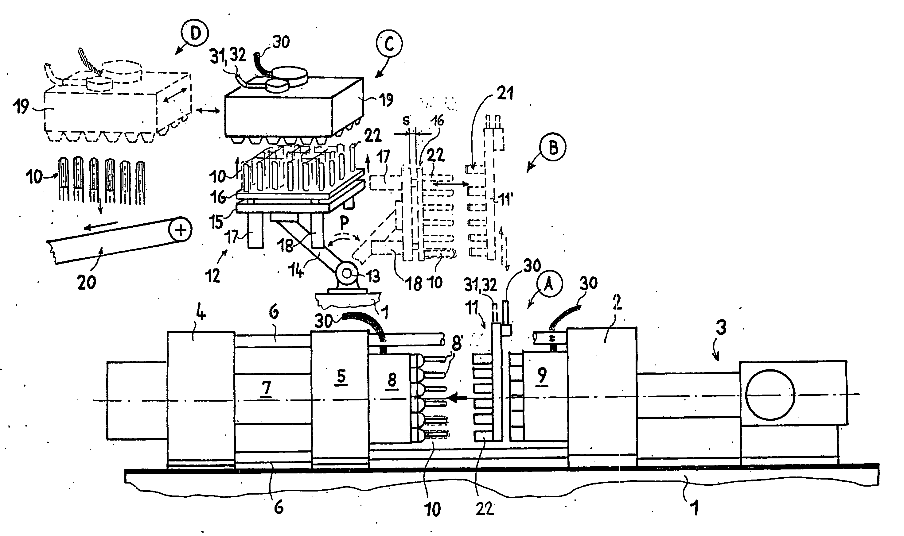
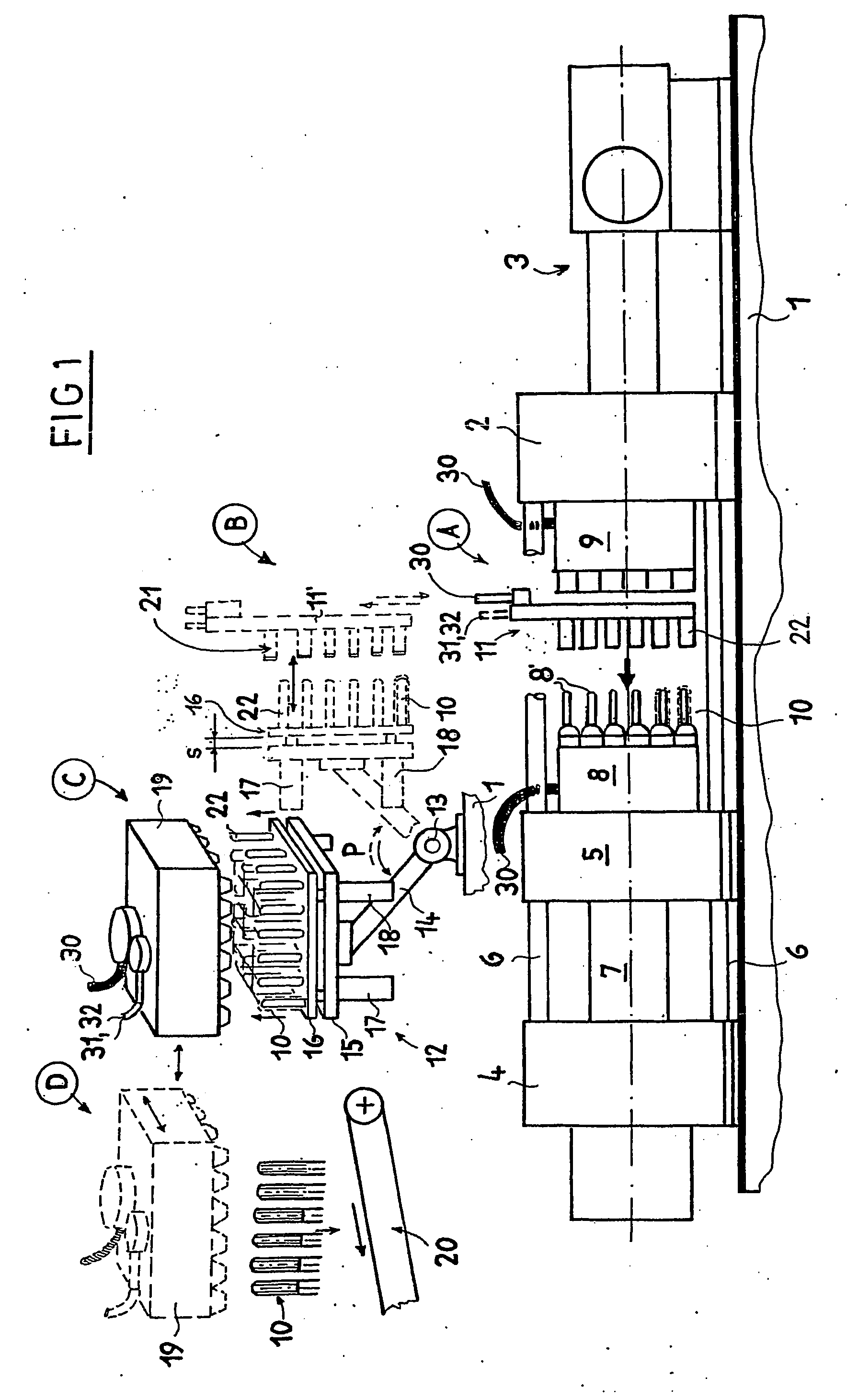
[0018] An especially advantageous first embodiment is characterized in that a slight swelling pressure is generated through the cooling pins. In view of the best possible thermal transition between the preforms and the inner wall area of the cooling sleeves, the objective is to introduce the preforms into the cooling sleeves without play, if possible. A solution in the state of the art is to develop the preforms conically on the outside, with the preforms being only introduced partially initially, pulled in gradually with appropriate negative pressure at the opposite side, and good wall contact with the cooling sleeve is maintained over the entire duration of the secondary cooling time. The big disadvantage is that the bottom parts of the preforms are cooled only very poorly from the outside. With the new solution, the complete introduction is performed dynamically with no time delay, if possible, i.e. essentially within seconds. The wall contact can be maintained during the remaind...

second embodiment

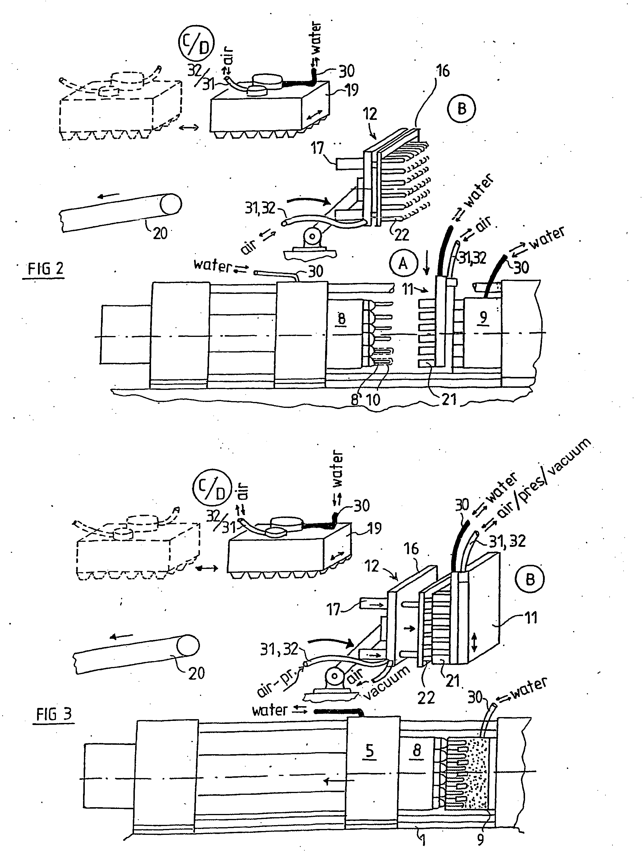
[0020] the inner cooling is performed by means of suction air through cooling pins arranged on a transfer gripper, which are introduced synchronously into the interior of the preforms after the removal device is moved out completely, with suction air remaining active after the intensive cooling during the transfer of the preforms from the removal device to a separate secondary cooling station until the preforms are transferred to the secondary cooler. During the intensive cooling, each cooling pin remains connected to a vacuum pump that actively suctions off warmed cooling air through the cooling pin. The intensive inner cooling is maintained for at least 2 to 7 seconds of cooling time and / or approximately 3% to 10% of the secondary cooling period until sufficient firmness of the outer skin of the preform. The intensive cooling is only a fraction of the entire secondary cooling. During the intensive cooling, the temperature is lowered on the average by 20 to 40° C. A severe prolong...

third embodiment

[0023] A third embodiment is characterized in that the device for an interior cooling has cooling pins of a controlled, displaceable supporting plate which can be introduced into the preforms, with the individual cooling pins being developed to yield into the direction of the introduction movement with respect to the preforms so that each cooling pin can be introduced with controlled force until it establishes contact with the inner mandrel part of the preforms. The cooling pins can be developed as blow mandrels and have a movably arranged contact head and a continuous air boring to the contact head, which runs into a blast air chamber between the blow mandrel and the contact head and is variable in size. Advantageously, each cooling pin has a compression spring to generate a controlled pressing power. The cooling pins are developed with a contact cooling head for the mechanical contacting and contact cooling of the corresponding interior mandrel part of the respective preform, with...


PUM

PropertyMeasurementUnit
glass temperatureaaaaaaaaaa
temperatureaaaaaaaaaa
surface temperatureaaaaaaaaaa

Abstract

The invention relates to a method and a device for the secondary treatment and the cooling of preforms (10) once they have been removed from the open mould halves (18, 9) of an injection moulding machine. The preforms are removed from the open moulds (18, 9) while still hot, by means of water-cooled cooling sleeves (21) of a removal device (11), and are subjected to intensive cooling during the duration of an injection moulding cycle. Both the entire inner side and the entire outer side of the blow-moulded part (10) are subjected to intensive cooling. Secondary cooling is then carried out, the duration thereof being equal to a multiple of the duration of an injection moulding cycle. After being removed from the casting moulds, the preforms are dynamically introduced into the cooling sleeves (21) until they fully touch the walls thereof. The inner cooling is carried out in a time-delayed manner.

Description

TECHNICAL FIELD [0001] The invention relates to a method for the secondary treatment and cooling of preforms after they have been removed from the open mould halves of an injection moulding machine, with the preforms being removed from the open moulds while still hot by means of water-cooled cooling sleeves of a removal device. The invention furthermore relates to a device for the secondary treatment and cooling of preforms after the removal from the upper mould halves of an injection moulding machine by means of water-cooled cooling sleeves of a removal device. STATE OF THE ART [0002] In the production of injection moulds, the cooling time is a determining factor for the total time of a full cycle. The main cooling preformance occurs still in the casting mould halves. Both casting mould halves are intensively water-cooled during the casting process so that the temperature of the injection moulds can be lowered already in the forms from approximately 280° C., at least in the border ...

Claims


Application Information

Patent Timeline
Patent Type & Authority Applications(United States)
IPC IPC(8): B29C45/38B29C71/00B29C45/72
CPCB29C45/7207B29C2045/7214B29K2105/253B29C49/6427B29C49/42421
Inventor WEINMANN, ROBERT
Owner NETABTAL MASCHEN
Why Eureka
Try Eureka