Doped ceramic materials and methods of forming the same

Inactive Publication Date: 2006-06-29
NAT UNIV OF SINGAPORE
View PDF24 Cites 7 Cited by
  • Summary
  • Abstract
  • Description
  • Claims
  • Application Information

AI Technical Summary

Benefits of technology

[0089] The doping step (b) causes infiltration of the dopant into the ceramic preform to thereby result in the formation of a compositional gradient whereby the amount of the dopant decreases in the direction from the first layer to the second layer within the transition layer. The desired amounts of dopant in the first layer and the second layer may be achieved by controlling the immersion time of the ceramic preform in the dopant solution or by varying the concentration of the dopant solution.
[0090] Uniform doping of a ceramic preform generally decreases sinterability of the preform. However, by forming a compositional gradient in the transitional layer of the ceramic preform, the sinterability of the ceramic preform can be maintained.
[0091] The compositional

Problems solved by technology

Most commercial alumina cutting tools are unsuitable for cutting at such a high speed due to accelerated flank wear of the alumina.
However, the addition of the dopant can decrease sinterability of the ceramic material.
Hot pressing can be an expensive process which may result

Method used


Image

  • Doped ceramic materials and methods of forming the same
  • Doped ceramic materials and methods of forming the same
  • Doped ceramic materials and methods of forming the same

Examples


example 1

Method of Forming Cr2O3 doped Al2O3 material

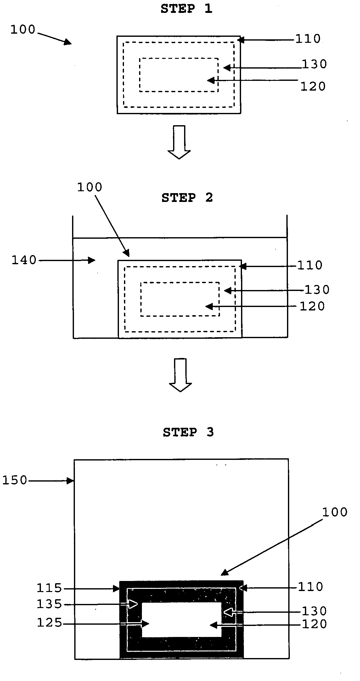
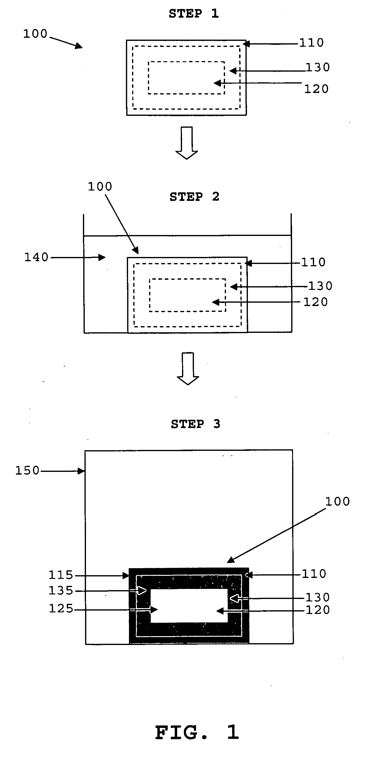
[0150]FIG. 1 shows the method steps of forming Cr2O3 doped Al2O3 material.

[0151] In Step 1, a high sinterability Al2O3 (alumina) preform 100 having a first layer 110, a second layer 120 and a transitional layer 130 connecting the first layer 110 and the second layer 120 was provided. The first layer 110, the second layer 120 and the transitional layer 130 form an integral structure and do not exist as distinct separate layers. The high sinterability Al2O3 preform 100 was provided by slip casting a colloidal suspension of Al2O3 powder (average particle size 0.18 μm) into a mould to form a green body, and pre-firing the green body at 850° C. for 1 hour to form the high sinterability Al2O3 preform. The Al2O3 preform has a relative density of 64% and is sanded to rectangular-shaped preforms measuring 17 mm×17 mm×6 mm in dimension.

[0152] In Step 2, the Al2O3 preform was immersed in a saturated solution chromic acid 140 for 1 hour to attain a...

example 2

Comparison of Cr2O3 doped Al2O3 Materials Having Cr2O3 Concentrations of 0.0, 0.6, 1, 2 and 3.5 mol % in the First Layer

[0157] The method in Example 1 was repeated to form Cr2O3 doped Al2O3 materials having Cr2O3 concentrations of 0.6, 1, 2 and 3.5 mol % in the first layer.

[0158] Undoped Al2O3 material was provided by slip casting a colloidal suspension of Al2O3 powder (average particle size 0.18 μm into a mould to form a green body, and pre-firing the green body at 850° C. for 1 hour to form the Al2O3 preform. The Al2O3 preform is subsequently sintered under vacuum at a temperature of 1450° C. for 3 hours to form the undoped Al2O3 material.

[0159] Table 1 below tabulates the values of relative density, grain size, hardness and fracture toughness of the Cr2O3 doped Al2O3 material at Cr2O3 concentrations of 0.0, 0.6, 1, 2 and 3.5 mol % in the first layer.

TABLE 1Cr2O3content inFracturefirst layerRelativeGrain SizeHardnessToughness(mol %)Density(μm)(GPa)(M Pa m1 / 2)0.0>99.5%4.6 ± 1....

example 3

Tool Life of Cutting Tool Inserts Formed from Cr2O3 doped Al2O3 Material and Commercial White Alumina material [Al2O3 with 3-5 vol % ZrO2]

[0166] A cutting tool insert formed from Cr2O3 doped Al2O3 material with a Cr2O3 content of 2.0 mol % in the first layer was produced in accordance with the method of Example 1 (referred to as Type C insert).

[0167] Two commercial white alumina [Al2O3 with 3-5 vol % ZrO2] cutting tool inserts (referred to as Types S and K), were also provided for comparison purposes.

[0168] The inserts C, S and K were used to cut medium-carbon steel at high cutting speeds of 1000 m / min without a coolant.

[0169] The average grain sizes, room temperature properties and tool life of the three inserts are listed in Table 2 below.

CuttingHard-FractureToolToolGrainnessToughnessLifeInsertsCompositionSize (μm)(GPa)(M Pa m1 / 2)(minutes)CAl2O33.7 ± 0.920.13.76.5(2 mol % Cr2O3)SAl2O3 with2.3 ± 1.116.02.64.0(3-5 vol % ZrO3)KAl2O3 with2.1 ± 0.815.43.83.0(3-5 vol % ZrO3)

[0170] ...


PUM

PropertyMeasurementUnit
Temperatureaaaaaaaaaa

Abstract

A doped ceramic material comprising: a first layer comprising ceramic material and an amount of dopant, a second layer comprising the ceramic material, and a transitional layer connecting the first layer and the second layer. The transitional layer comprises the dopant in an amount which decreases in a direction from the first layer to the second layer. A method of forming the doped ceramic material is also disclosed.

Description

REFERENCE TO RELATED APPLICATION [0001] This application claims the benefit of U.S. Provisional Application Ser. No. 60 / 632,244 filed Dec. 1, 2004.TECHNICAL FIELD [0002] The present invention relates to doped ceramic materials and methods of forming the same. The present invention also relates to cutting tools formed from the doped ceramic materials. BACKGROUND [0003] Ceramic materials for engineering applications generally possess properties such as high sintered densities, fine grain sizes, high hardness and reasonable fracture toughness. These properties enable ceramic materials to be employed in tools for cutting materials such as metals. one commonly used ceramic material for such an application is alumina. [0004] In high speed cutting of carbon steel, a cutting speed as high as 1000 m / min may be desired. Most commercial alumina cutting tools are unsuitable for cutting at such a high speed due to accelerated flank wear of the alumina. The resistance of the alumina can be improv...

Claims


Application Information

Patent Timeline
IPC IPC(8): B32B19/00B32B9/00B28B3/00
CPCB23B2226/18C04B35/64C04B41/009C04B41/5033C04B41/87C04B2111/00405C04B2235/3241C04B2235/5445C04B2235/6027C04B2235/6581C04B2235/661C04B2235/75C04B2235/77C04B2235/785C04B2235/786C04B2235/96C04B41/4535C04B41/455C04B41/457C04B35/10C04B38/00
Inventor LIM, LEONG CHEWLIU, PING
Owner NAT UNIV OF SINGAPORE
Why Eureka
Try Eureka