

Method for producing a ceramic crucible
a technology of ceramic crucibles and crucibles, which is applied in the field of ceramic crucible production methods, can solve the problems of only being used, unable to meet the requirements of use, and known methods are relatively cost-intensive, and achieve the effects of low cost, small dimensional tolerance, and easy and cheap production
- Summary
- Abstract
- Description
- Claims
- Application Information
AI Technical Summary
Benefits of technology
Problems solved by technology
Method used
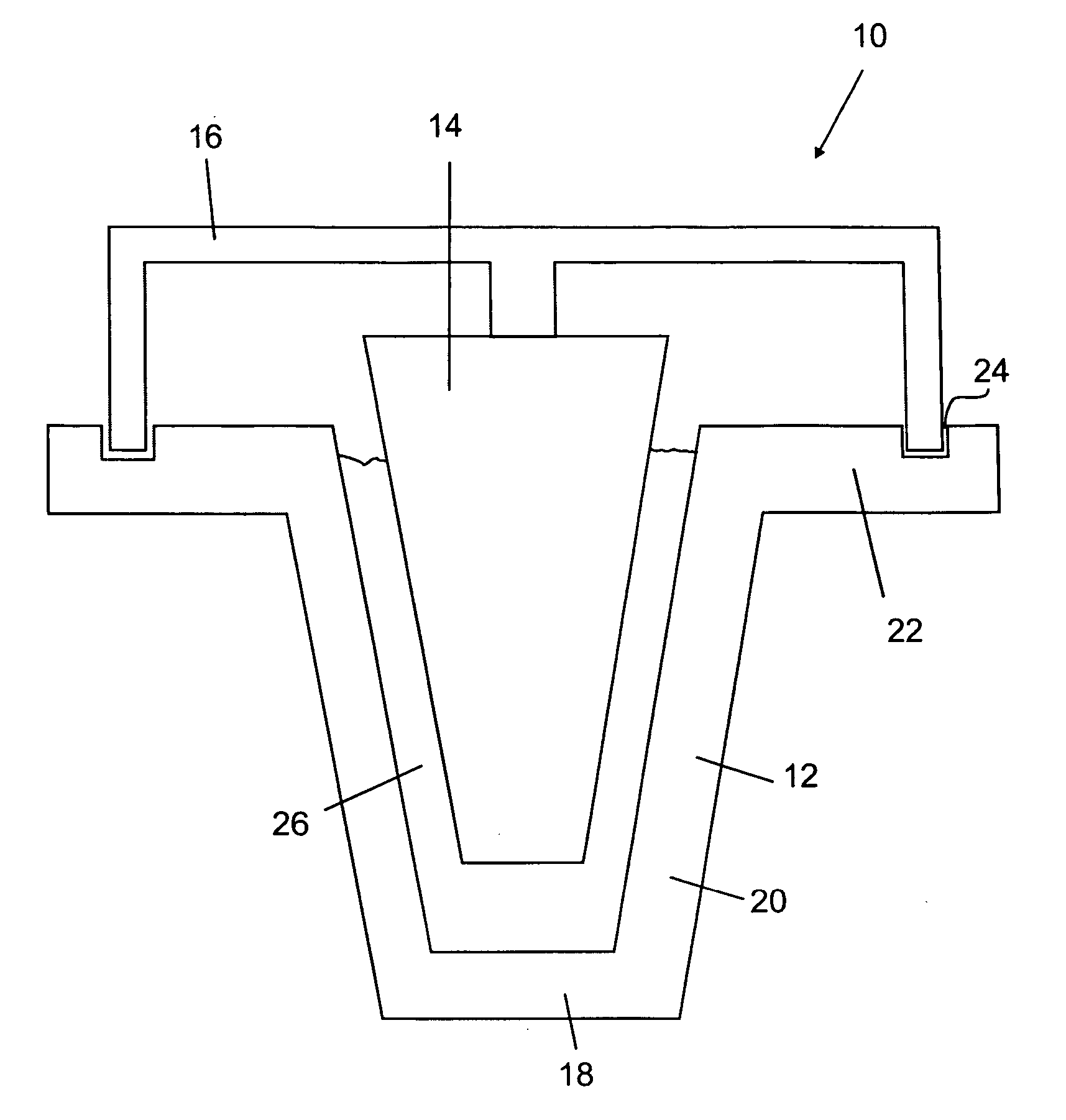
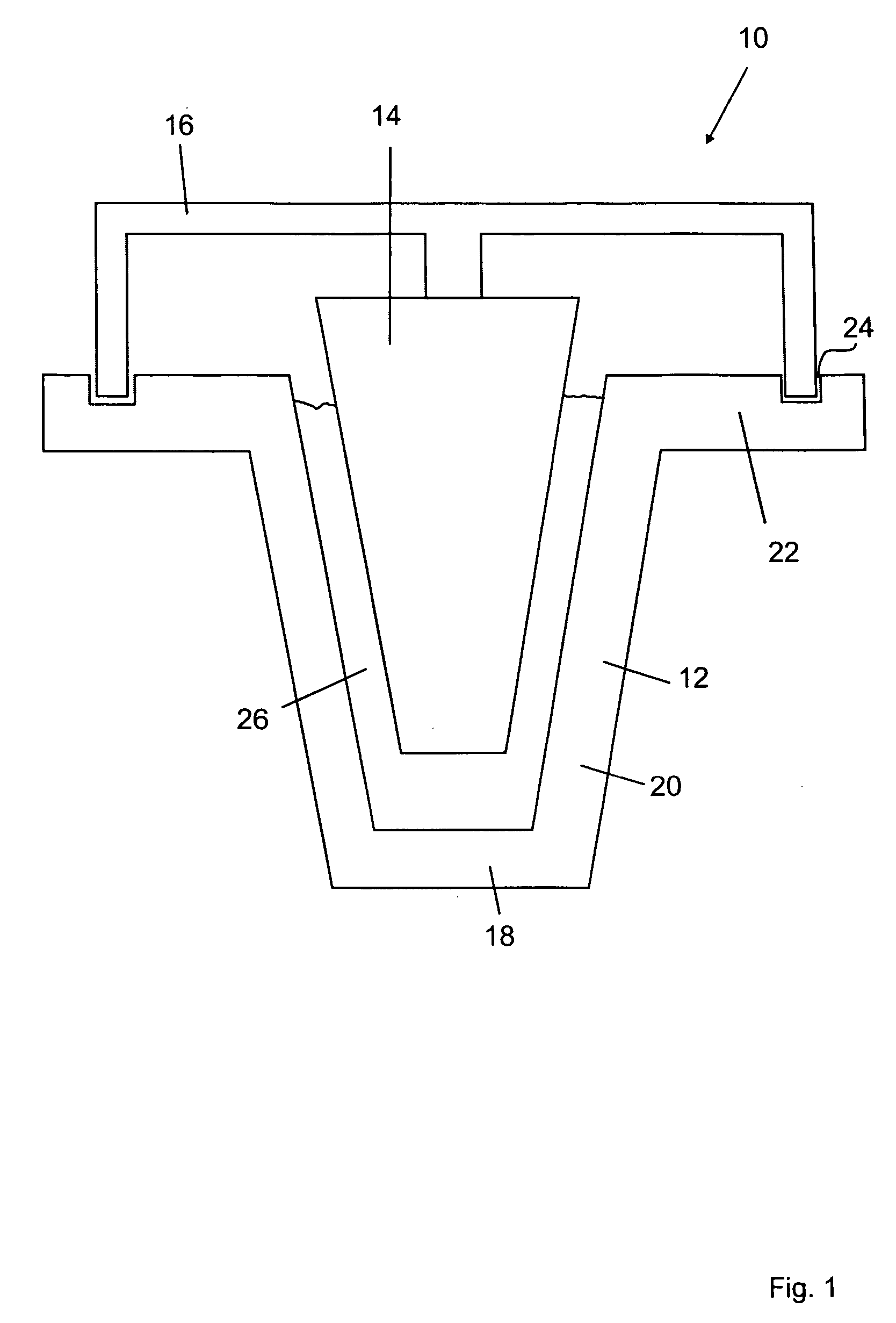
Image

Examples
example 1
Practical Example 1
[0084] A method is described below for producing a ceramic crucible according to a practical example of the present invention. An aqueous silicon dioxide sol is mixed with aluminum oxide powder and mullite powder by stirring; glycerol is added.
[0085] The median value (d50) of the distribution of the diameters of the SiO2 particles in the aqueous SiO2 amounts to 8 nm. The diameters of the aluminum oxide powder particles are less than 10 μm and the diameters of the mullite powder particles are less than 80 μm. Such a sol is produced industrially, for example by acidifying aqueous sodium silicate solutions, passing the solution over cation exchangers and alkalizing the resultant sol. Such a sol is sold by CWK as Kostrosol 08 / 30.
[0086] The mixture has the composition stated in Table 1:
TABLE 1Materialgwt. %Mullite10050.9Aluminium oxide4522.9SiO2 sol5025.4Glycerol1.50.8Total196.5100.0
[0087] The mixture is a freeze-castable slip, i.e. a special solidifiable slip. The...
example 2
Practical Example 2
[0093] A further practical example of a method according to the invention is described below. First of all, an aqueous SiO2 sol is mixed with aluminum oxide, mullite and Nb powder by stirring; glycerol is added. The diameters of the aluminum oxide, mullite and SiO2 particles are those stated in practical example 1. The diameter of the niobium particles is less than 40 μm.
TABLE 2Materialgwt. %Mullite10050.4Aluminium oxide4522.7SiO2 sol5025.2Glycerol1.50.7Nb21.0Total198.5100.0
[0094] The slip produced in this way is poured into a metallic casting mould as in practical example 1 and frozen at −40° C. in the freezing compartment. The resultant preform is demoulded and then dried in a drying cabinet at 60° C., 1013 hPa and 30% relative atmospheric humidity. The preform is then air-sintered for 3 hours at 1200° C. During sintering the Nb powder oxidises (due to the presence of atmospheric oxygen) with an increase in volume to yield niobium pentoxide.
example 3
Practical Example 3
[0095] A further practical example of a method according to the invention is described below. First of all an aqueous SiO2 sol is mixed with aluminium oxide, mullite, Nb and AlMg5 powder by stirring. The diameter of the AlMg5 powder particles is less than 80 μm. The diameters of the other particles correspond to those stated in practical example 2.
TABLE 3Materialgwt. %Mullite10045.8Aluminium oxide4520.6SiO2 sol5022.9Glycerol1.50.7Nb20.9AlMg5209.1Total218.5100.0
[0096] The slip produced in this way is poured into a metallic casting mould as in practical example 1 and frozen at −40° C. by cryostat. The resultant preform is demoulded and then dried in a drying cabinet at 60° C., 1013 hPa and 30% relative atmospheric humidity. The preform is then firstly heated for 2h to 600° C. to 700° C. and then air-sintered for 3 hours at 1200° C. While the preform has a temperature of 600° C. to 800° C., the AlMg5 powder liquefies and oxidises with an increase in volume to yield...
PUM
| Property | Measurement | Unit |
|---|---|---|
| diameter | aaaaa | aaaaa |
| diameter | aaaaa | aaaaa |
| melting points | aaaaa | aaaaa |
Abstract
Description
Claims
Application Information