Gas combustion treatment method and apparatus therefor

a gas combustion treatment and gas combustion technology, applied in the direction of combustion types, separation processes, emission prevention, etc., can solve the problems of troublesome operation procedures, leakage of nhsub>3 /sub>to the downstream side, and inability to achieve nhsub>3 /sub>, etc., to reduce nox, reduce environmental load, and simplify the effect of treatment system

Inactive Publication Date: 2006-06-29
MITSUBISHI HEAVY IND LTD +1
View PDF24 Cites 15 Cited by
  • Summary
  • Abstract
  • Description
  • Claims
  • Application Information

AI Technical Summary

Benefits of technology

[0011] In view of the above-described problems, the present inventors made intensive investigations for the purpose of developing a method for the treatment of an ammonia-containing gas and a hydrogen sulfide-containing gas in which these off-gases can be treated at a reduced running cost, the emission of nitrogen oxides (NOx) and the like can be effectively suppressed so as to be lower than required environmental load levels, and the apparatus used therefor is simple and small-sized, has high reliability, and is easy of operation and maintenance.
[0016] The present invention can provide a three-stage combustion apparatus in which the combustion treatment of off-gases resulting from the purification of coal gasification gas can be carried out very efficiently.
[0019] The three-stage combustion apparatus of the present invention is divided into three stages. Starting from its upstream end for gas introduction, the first stage comprises a first combustion section for burning NH3 off-gas, the second stage comprises a nitrogen oxide reduction section for reducing NOx, and the third stage comprises a second combustion section for burning H2S off-gas. This three-stage construction makes it possible to carry out the combustion treatment of NH3 off-gas and H2S off-gas in the same combustion apparatus while giving low environmental load values.
[0020] Since the present invention enables the sequential combustion treatment of NH3 off-gas and H2S off-gas, the necessity of treating them separately is eliminated to bring about a simplification of the treatment system. Moreover, by burning NH3 off-gas, the cost for the disposal of ammonia water is made unnecessary. Furthermore, by providing a bypass section for H2S off-gas or NH3 off-gas, the production of NOx is reduced. In addition, the effect of heat recovery from combustion furnace waste gas can be expected.

Problems solved by technology

However, storage type combustion furnaces have problems in that they require a valve mechanism for carrying out operation while changing a plurality of flow paths in order to maintain the effectiveness of heat exchange and its operating procedure is troublesome.
Moreover, they are disadvantageous from the viewpoint of reliability ensuring freedom from troubles such as failure.
On the other hand, when conventional storage type combustion furnaces (at 1,000° C.) are used for the combustion treatment of NH3 off-gas, the complete combustion treatment of NH3 cannot be achieved to cause a leak of NH3 to the downstream side.
Although a high combustion temperature (about 1,500° C.) is required to decompose NH3 completely, the operating temperature of storage type combustion furnaces has been limited to about 1,000° C. owing, for example, to the endurable temperature limits of heat reservoirs comprising mullite and cordierite (high-temperature ceramic materials).
However, in order to maintain a high temperature of about 1,000° C. or above under a reducing atmosphere, it is necessary to burn a large amount of additional fuel.
Moreover, a large-sized combustion apparatus adapted for high-temperature conditions is required, and this is not economical from the viewpoint of operation and equipment investment.

Method used


Image

  • Gas combustion treatment method and apparatus therefor
  • Gas combustion treatment method and apparatus therefor
  • Gas combustion treatment method and apparatus therefor

Examples


Embodiment Construction

[0025] Specific embodiments of the gas combustion method in accordance with the present invention will be described below with reference to the accompanying drawings.

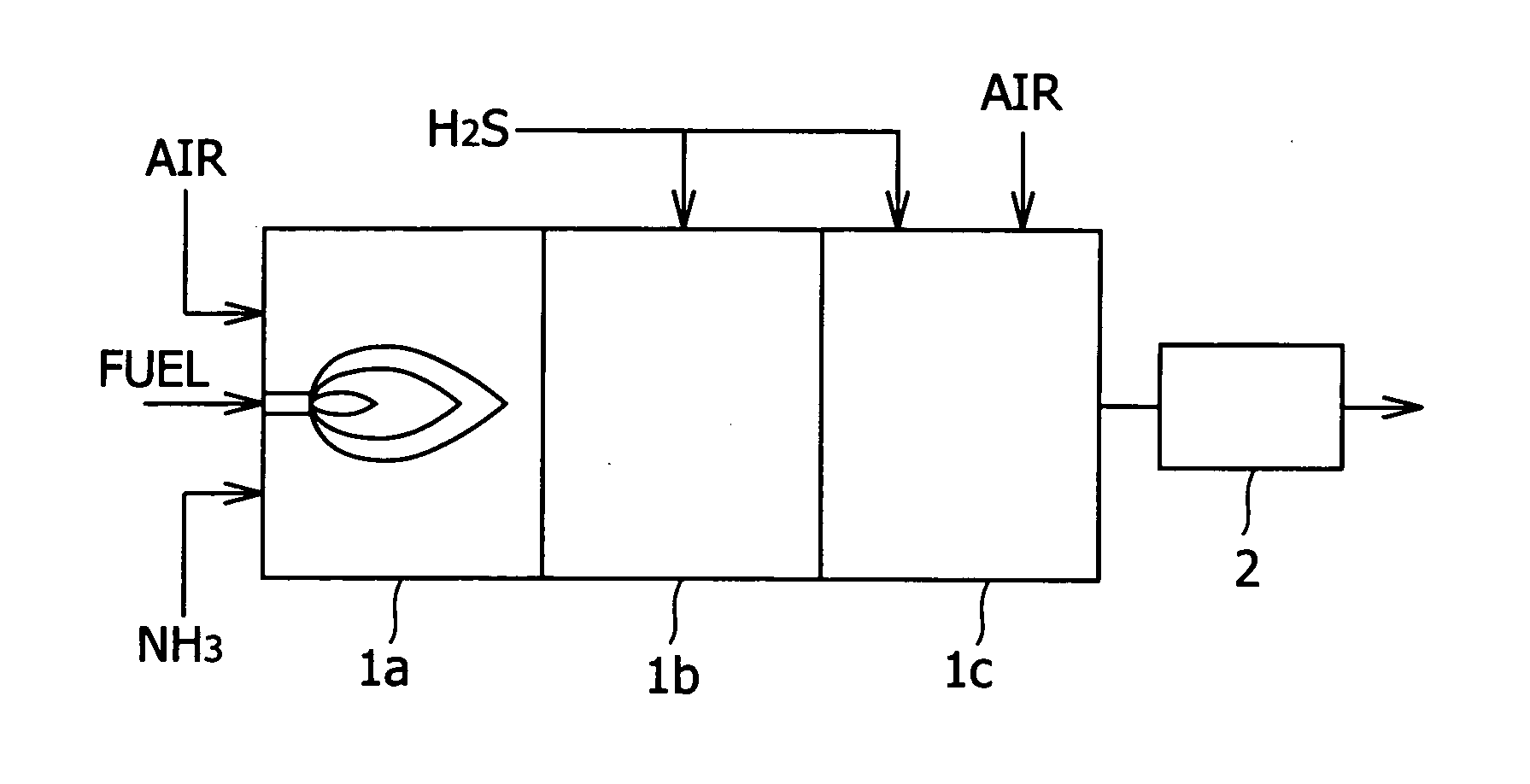
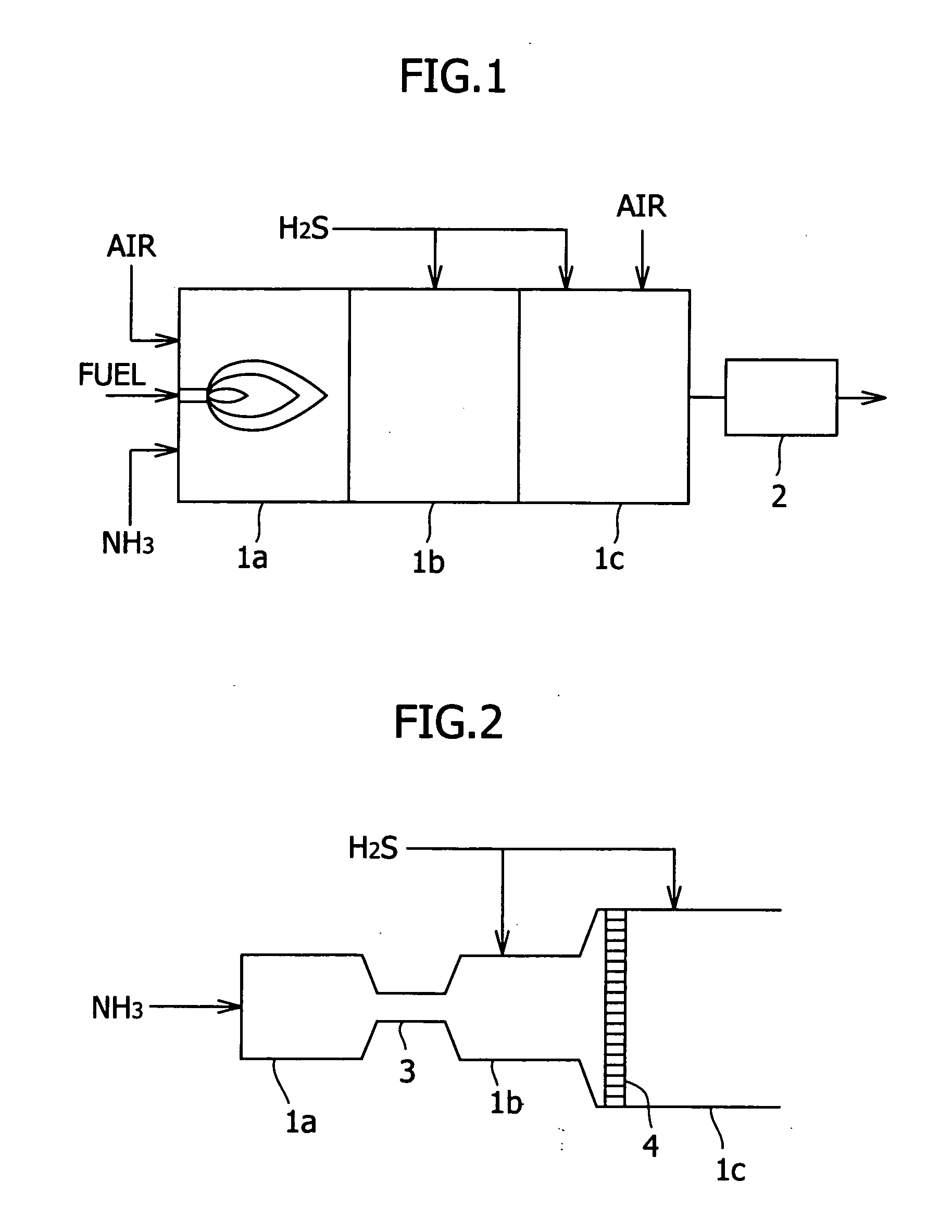
[0026]FIG. 1 is a schematic view illustrating an example of a combustion apparatus suitable for carrying out the combustion treatment method of the present invention. When viewed from its upstream end at which ammonia and a fuel are introduced, the combustion apparatus of this embodiment is equipped with a first combustion section 1a, a nitrogen oxide reduction section 1b and a second combustion section 1c in that order. In first combustion section 1a, an ammonia (NH3)-containing gas is introduced together with a fuel. Since this combustion apparatus is of a direct-burning type, a fuel is introduced in order to cause combustion in the combustion furnace, and this fuel is usually injected through a nozzle. At the same time, an oxygen-containing gas comprising air or the like is introduced in order to burn the fuel and a...


PUM

PropertyMeasurementUnit
temperatureaaaaaaaaaa

Abstract

A gas combustion treatment method for the combustion treatment of an ammonia-containing gas and a hydrogen sulfide-containing gas, the method comprising a first combustion treatment step in which the ammonia-containing gas, together with a fuel, is introduced and burned; a nitrogen oxide reduction step downstream of the first combustion treatment step, in which a portion of the hydrogen sulfide-containing gas or the ammonia-containing gas is introduced and the nitrogen oxides produced in the first combustion treatment step are reduced in a reducing atmosphere; and a second combustion treatment step downstream of the nitrogen oxide reduction step, in which the remaining hydrogen sulfide-containing gas, together with air, is introduced and burned. The present invention provides a combustion apparatus suitable for use as a combustion furnace for off-gases resulting from the wet purification of coal gasification gas.

Description

CROSS REFERENCE TO A RELATED APPLICATION [0001] This application is a divisional of U.S. patent application Ser. No. 10 / 245,326, filed Sep. 18, 2002, now allowed, which claims priority to Japanese patent application No. 2001-329190, filed Oct. 26, 2001, both of which are hereby incorporated by reference in their entirety.FIELD OF THE INVENTION [0002] This invention relates to gas combustion treatment methods and gas combustion apparatus. More particularly, it relates to a combustion apparatus suitable for use as a combustion furnace for off-gases resulting from the wet purification of coal gasification gas, and a combustion method therefor. BACKGROUND OF THE INVENTION [0003] When coal is gasified and used as a fuel for electric power generation, sulfur compounds (e.g., hydrogen sulfide and carbonyl sulfide) and nitrogen compounds such as ammonia are contained in the product gas. From the viewpoint of environmental protection and corrosion prevention, these compounds are removed in w...

Claims


Application Information

Patent Timeline
Patent Type & Authority Applications(United States)
IPC IPC(8): F23D14/62C01B32/50F23C99/00F23G7/06F23J7/00F23J15/00
CPCB01D53/52B01D53/58F23G7/065F23J7/00F23J15/006F23J2215/10Y02P20/129
Inventor HARADA, MASAHIROSUSAKI, MAKOTOISHIDA, KAZUONAGANO, HAJIMEHIRANO, MASAHIROSUZUMURA, HIROSHIHONJO, SHINTAROKOYAMA, YOSHINORIYOKOHAMA, KATSUHIKOSUEHIRO, MITSUGI
Owner MITSUBISHI HEAVY IND LTD
Why Eureka
Try Eureka