High resolution flow cytometer

a flow cytometer, high-resolution technology, applied in the field of high-resolution flow cytometers, can solve the problems of not straight, cell source conduit, and still remain with respect to the resolving capacity of convention flow cytometers, and achieve the effect of increasing the resolution of flow cytometers and increasing the homogeneity of isolated populations

Active Publication Date: 2006-06-29
XY
View PDF99 Cites 29 Cited by
  • Summary
  • Abstract
  • Description
  • Claims
  • Application Information

AI Technical Summary

Benefits of technology

[0020] Accordingly, the broad object of the invention can be to provide an increased resolution flow cytometer ...

Problems solved by technology

Even though conventional flow cytometers for the separation of cells or particles have been improved over the past several years significant problems still remain with respect to the resolving capacity of convention flow cytometers.
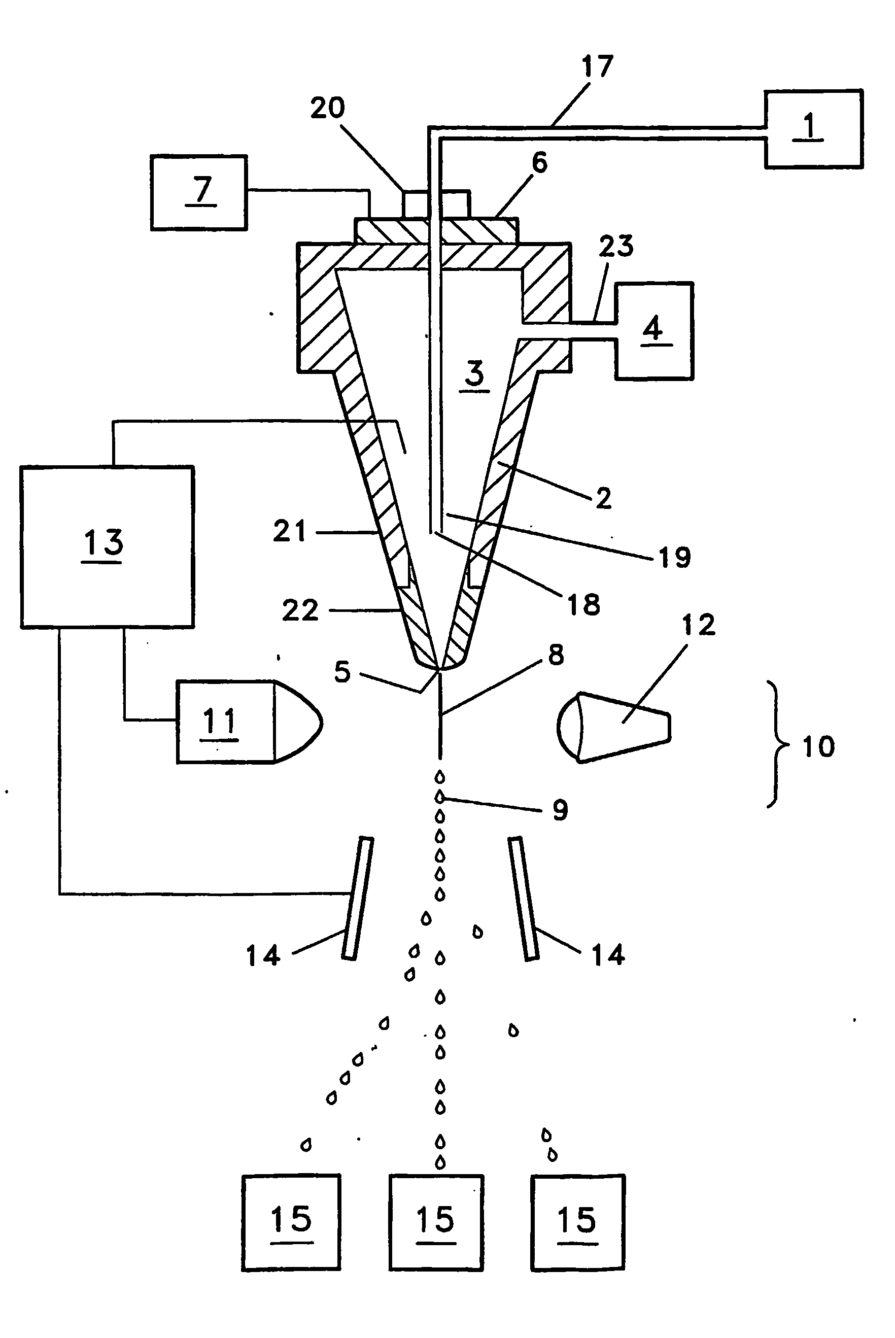
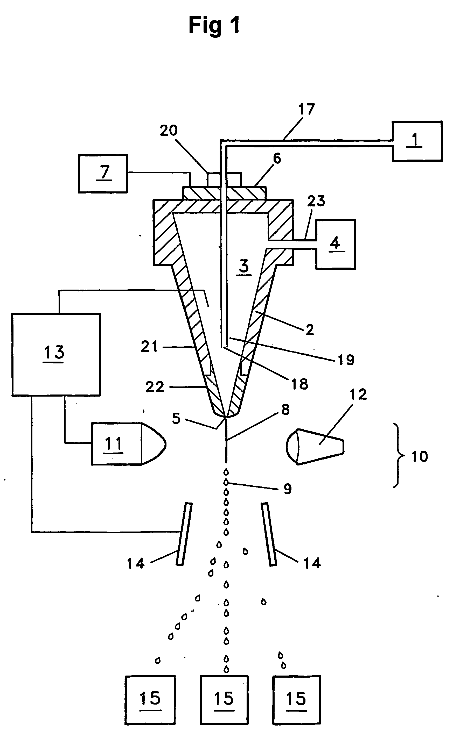
A significant problem with conventional flow cytometer technology as shown by FIG. 1 may be that the fluid source (4) along with the associated fluid source conduit(s)(23) introduces fluid (3) into the nozzle (2) substantially perpendicular to the flow of the fluid (3) within the nozzle (2).
A second significant problem with conventional flow cytometer technology as shown by FIG. 1 may be that the cell source conduit (17) between the cell source (1) and the nozzle (2) is not straight.
A third significant problem with conventional flow cytometer technology as shown by FIG. 1 may be that the cell source conduit (17) is too long.
A fourth significant problem with conventional flow cytometer technology as shown by FIG. 1 may be that the cell source conduit (17) and in particular the particle injector (19) portion of the cell source conduit may not be individually replaceable.
A fifth significant problem with conventional flow cytometer technology can be that there may be a connector (20) mounted to the entry end of the particle injector (19) portion of the cell source conduit (17) to couple the injector portion (19) with the cell source fluid conduit (17).
Even zero-dead volume connectors or couplers can introduce sufficient deformation or non-concentricity to the cell source conduit interior surface to allow particles or debris to adhere, cling, attach, or otherwise become immobilized at the location of the connector (20) resulting in potential cross contamination between sample populations transferred in the cell source fluid stream, or causing restrictions or otherwise altering the configuration of the cell source fluid path.
A sixth significant problem with conve...

Method used


Image

  • High resolution flow cytometer
  • High resolution flow cytometer
  • High resolution flow cytometer

Examples


Embodiment Construction

[0042] The invention involves a high resolution flow cytometer that can increase resolving power to separate mixed populations of cells, sperm cells, or particles from each other based upon various cell or particle characteristics individually or in combination.

[0043] As such, while particular examples of the invention are provided that describe the invention in the context of separating sperm cells, or separating bovine or equine intact live sperm cells, it should be understood that the enhanced resolution technologies described can have application with respect to separation of various types of flow separable particles, including, but not limited to, cells, spermatozoa, or sperm nuclei, collected, handled, or stored in a variety of ways.

[0044] X-chromosome bearing and Y-chromosome bearing populations of spermatozoa should further be understood to encompass enriched populations of flow separated or sorted spermatozoa obtained from a male of a species of mammal including, but not ...


PUM


Abstract

high resolution particle differentiation process and separation system that provides enhanced resolution of particles based upon selected particle characteristics. In particular, the system may include an enhanced resolution flow cytometer. In an embodiment, the invention can include at least one fluid source conduit (24) that introduces 0 fluid source stream (24) into an enhanced resolution nozzle (25) at an angle that enhances particle resolution by the cell sensing system (13).

Description

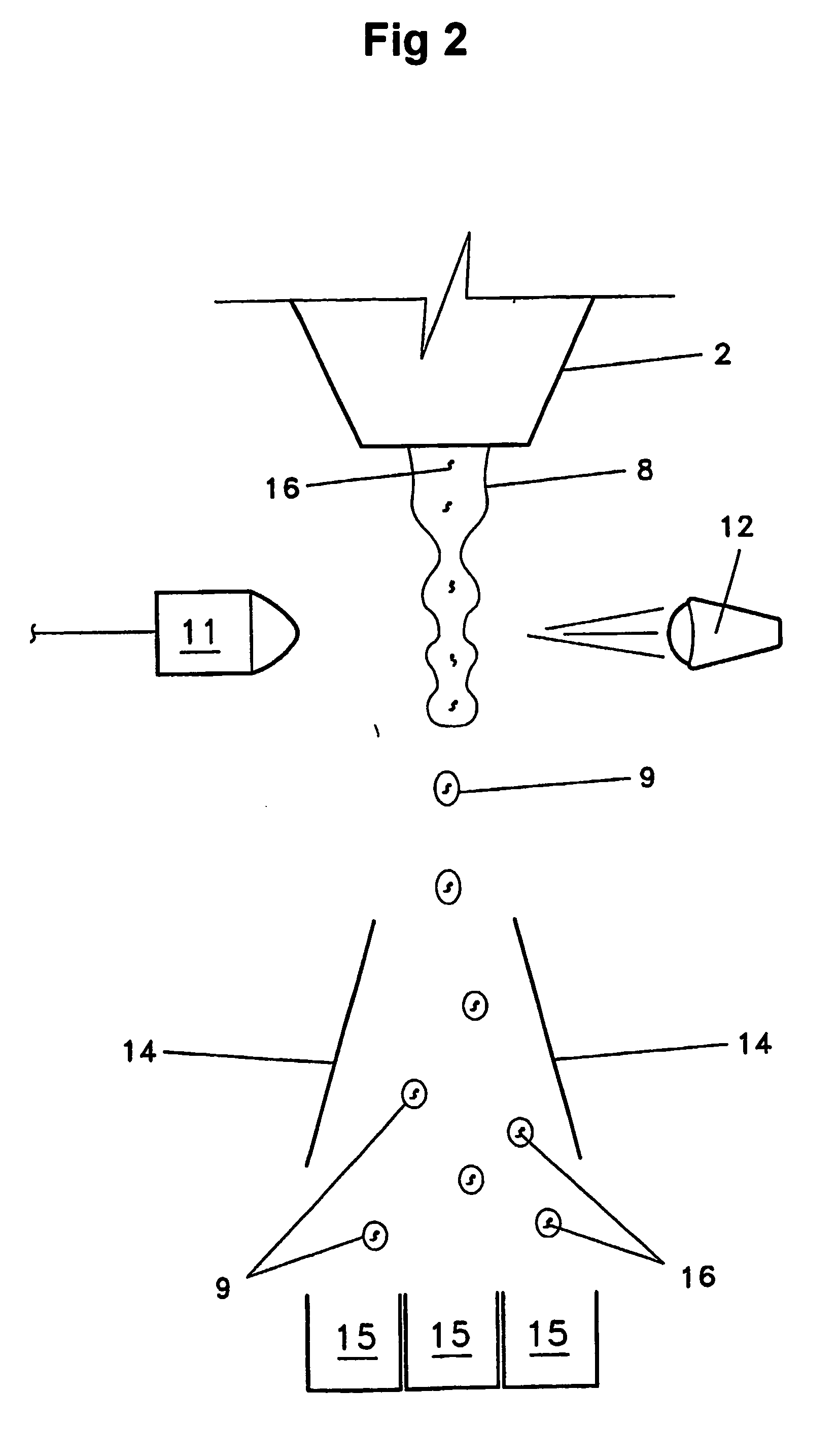
TECHNICAL FIELD [0001] High resolution differentiation and separation of particles based upon particle characteristics. Specifically, high resolution differentiation and separation of sperm cells into X-chromosome bearing and Y-chromosome bearing populations or increased homogeneity. BACKGROUND [0002] Effective preselection of sex has been accomplished in many species of mammal following the development of safe and reliable methods of separating sperm cells into enriched X chromosome bearing and Y chromosome bearing populations. Separation of X chromosome bearing sperm cells from Y chromosome bearing sperm cells can be accomplished as disclosed herein and as disclosed by various international patent applications, for example: WO 98 / 34094, WO 99 / 33956, WO 99 / 42810, WO 00 / 06193, WO 01 / 40765, WO 01 / 85913, WO 02 / 43486, WO 02 / 43574, each hereby incorporated by reference herein. [0003] Now referring to FIGS. 1 and 2, a conventional technology flow cytometer provides a particle or cell sou...

Claims


Application Information

Patent Timeline
IPC IPC(8): G01N33/48C12M1/00C12M1/34C12Q1/06G01N15/14
CPCG01N15/1404Y10T436/101666G01N33/56966
Inventor EVANS, KENNETH M.
Owner XY
Why Eureka
Try Eureka