Evaporator designs for achieving high cooling performance at high superheats

a superheat and evaporator technology, applied in indirect heat exchangers, lighting and heating apparatus, laminated elements, etc., can solve the problems of reducing cooling capacity, limiting the use of one or the other fins or dimples throughout all of the tubes in an evaporator, and reducing cooling capacity, so as to improve heat exchange efficiency. , the effect of improving the thermal energy exchang

Inactive Publication Date: 2006-07-06
DELPHI TECH INC
View PDF11 Cites 10 Cited by
  • Summary
  • Abstract
  • Description
  • Claims
  • Application Information

AI Technical Summary

Benefits of technology

[0007] The invention provides a laminate-type evaporator having first and second tanks and fabricated from a plurality of plates. Each plate has upstream and downstream side edges with an interior portion recessed relative thereto. The plates are disposed in pairs with the side edges of each pair in abutting engagement with one another and the interior portions defining a passageway between each pair. The pairs are spaced along the tanks in first and second groups, and the passageways are in fluid communication with the tanks for permitting a fluid to flow between the tanks through the passageways. A thermal energy exchange occurs between the fluid and a cross-flow of air through the first and second groups from the upstream to downstream side edges. Dimples extend from the interior portions into the passageways of the first group. Interior fins are disposed against the interior portions and extend to the upstream and downstream side edges, which enhances the thermal energy exchange between the fluid and the cross-flow of air between the upstream and downstream side edges of the second group of plates.

Problems solved by technology

While interior fins and “bumped” or “dimpled” surfaces increase heat exchange within the evaporator, limiting use of one or the other of the fins or dimples throughout all of the tubes in an evaporator is not necessarily the optimum way to maximize heat exchange.
This reduces cooling capacity and causes the temperature distribution of the discharge air to become more non-uniform.
Another problem with dimpled evaporators is that under certain transient vehicle operating conditions, vapor flowing over the dimples gives rise to a pure tone noise or “whistle” emanating from the evaporator.

Method used


Image

  • Evaporator designs for achieving high cooling performance at high superheats
  • Evaporator designs for achieving high cooling performance at high superheats
  • Evaporator designs for achieving high cooling performance at high superheats

Examples


Embodiment Construction

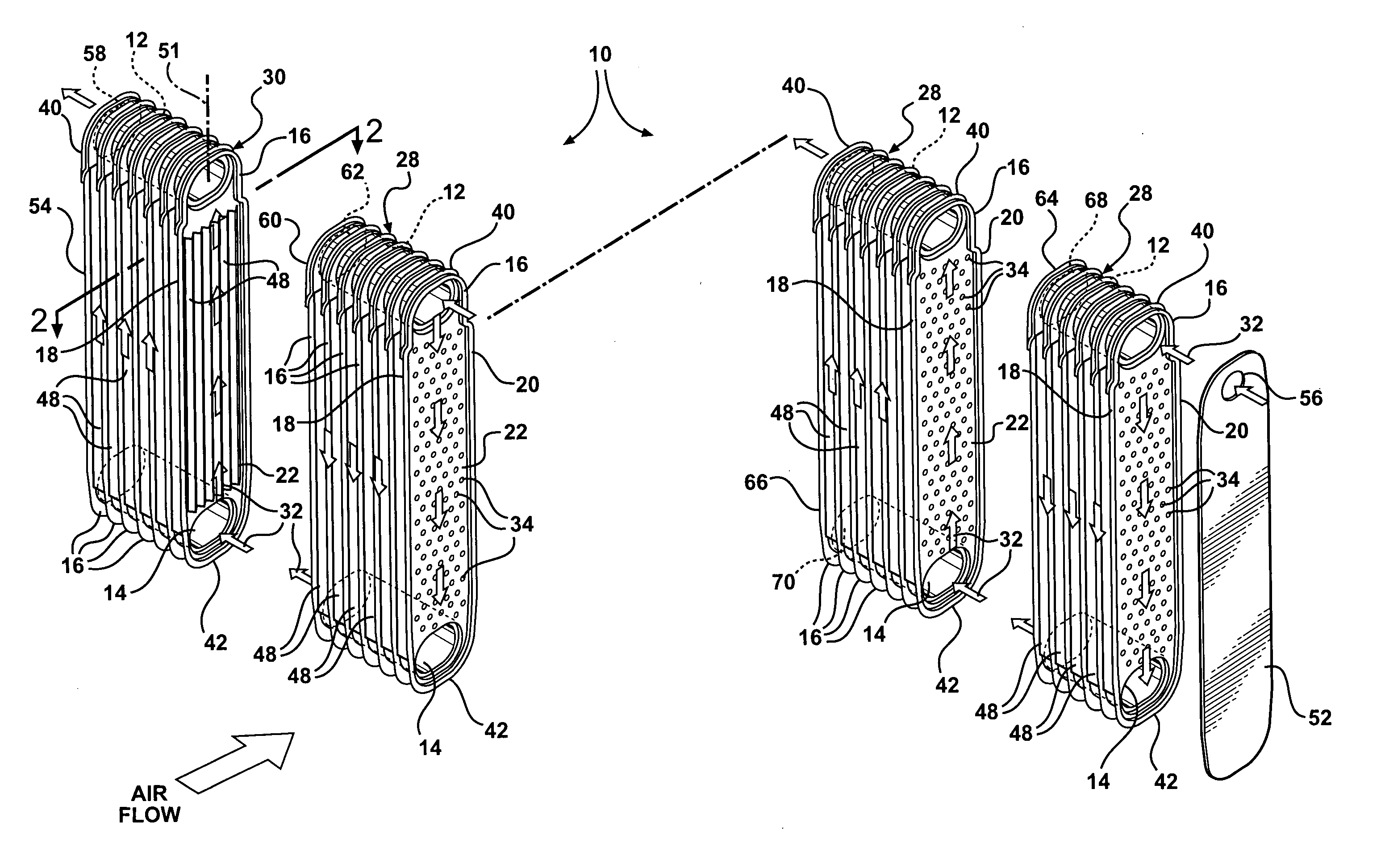
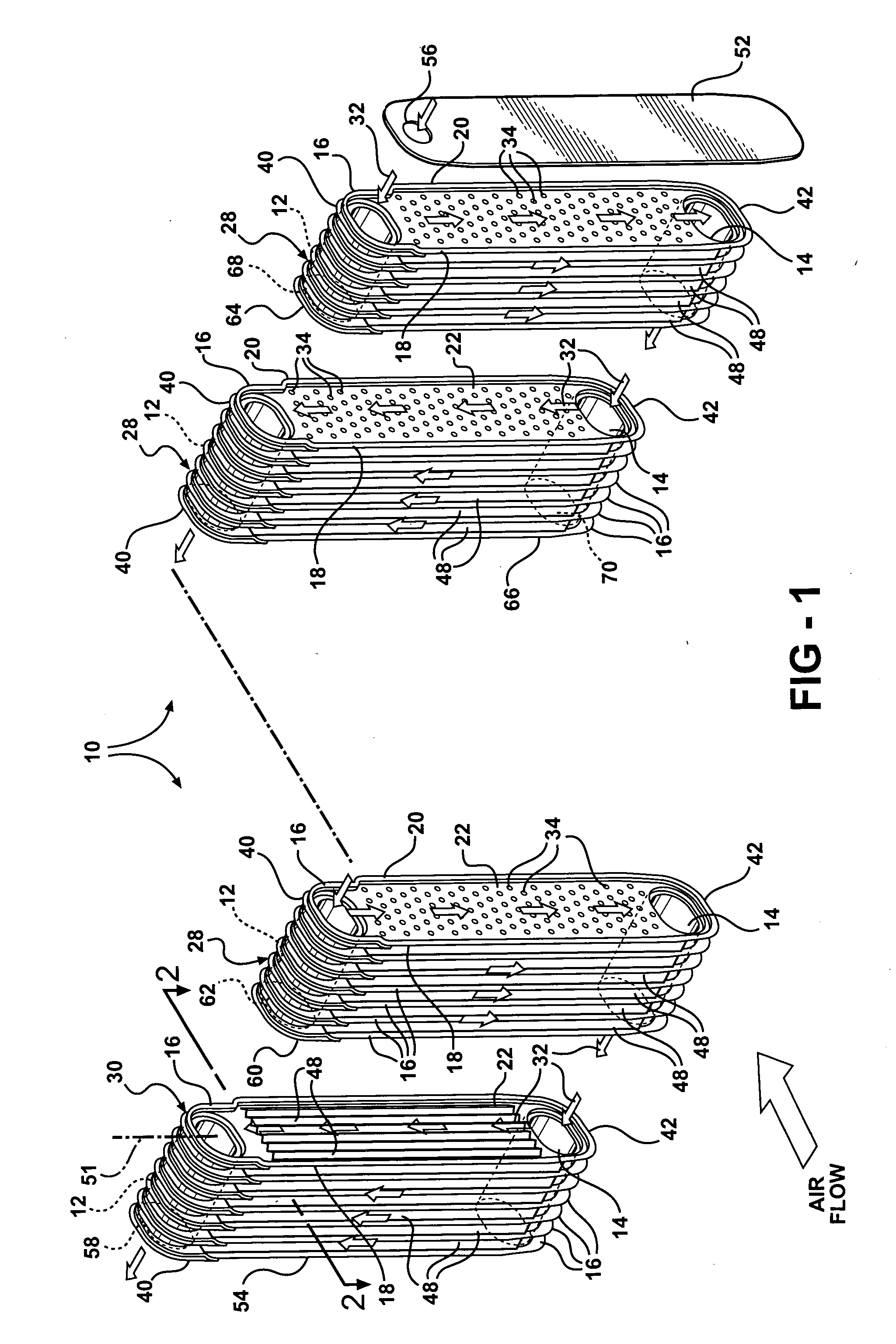
[0018] Referring now to the Figures, wherein like numerals indicate like or corresponding parts throughout the several views, a laminate-type evaporator is generally shown at 10 in FIGS. 1 through 3. The evaporator 10 includes upper and lower or first and second tanks 12, 14 and is fabricated from a plurality of plates 16.

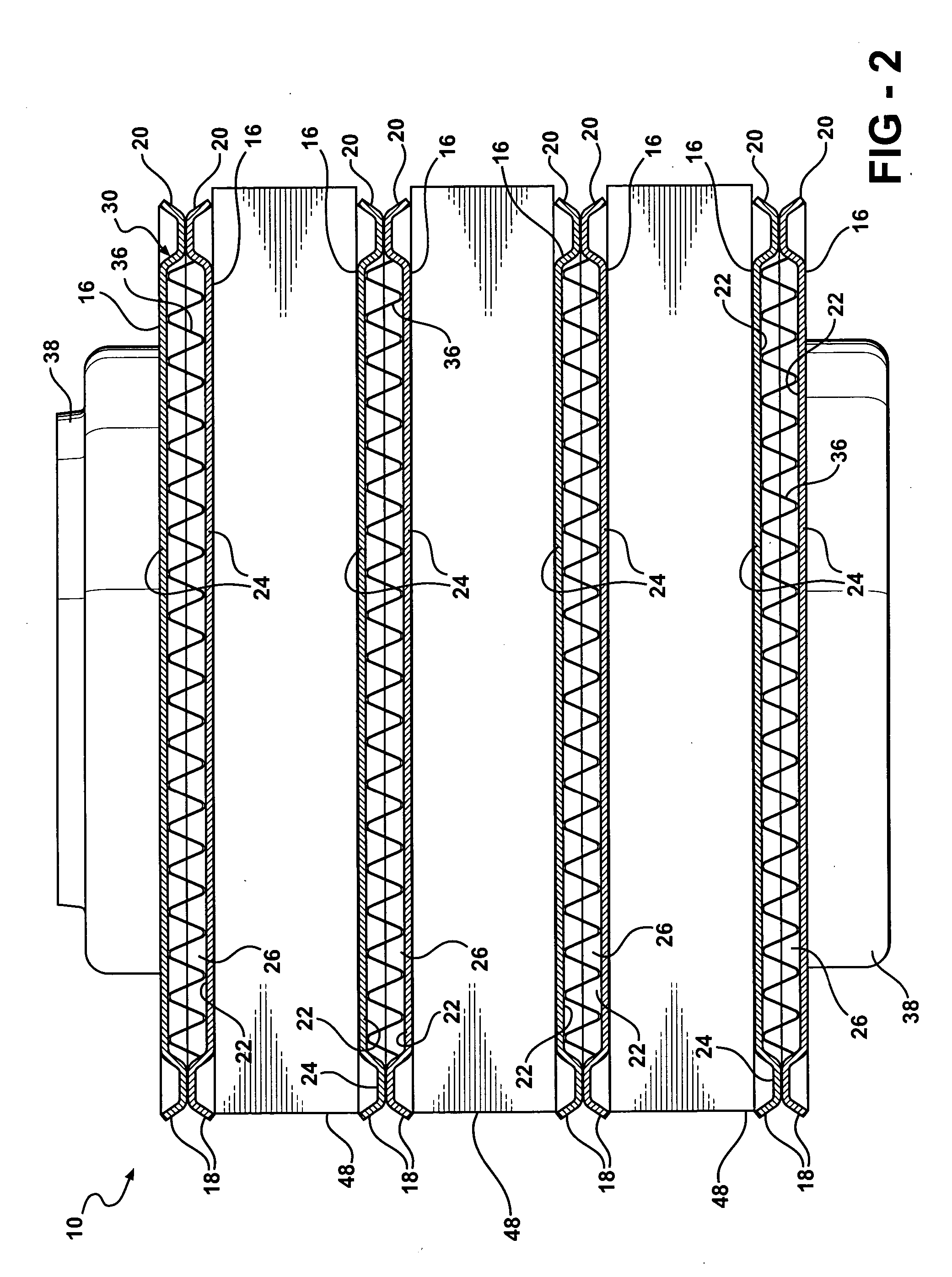
[0019] Each of the plates 16 has upstream and downstream side edges 18, 20 with an interior portion 22 recessed relative thereto. As shown in FIG. 2, the plates 16 are disposed in pairs 24, with the side edges 18 and 20 in overlapping and abutting engagement with one another such that the interior portions 22 define a passageway 26 between the plates 16 in each pair 24.

[0020] Referring now to FIG. 1, the pairs 24 are spaced along the tanks 12, 14 in first and second groups 28, 30 with the passageways 26 in fluid communication with the tanks 12, 14. The manner in which the passageways 26 are interconnected permits a fluid, or fluid stream of refrigerant, 32 to flo...


PUM


Abstract

An evaporator includes plates disposed in pairs in first and second groups, along spaced tanks. Dimples extend from the interior portions in the first group, and interior fins are disposed against the interior portions of the second group. The dimples enhance the distribution of liquid refrigerant in the passageways and the thermal energy exchange between ambient air and an upstream, low vapor quality flow of fluid passing between upstream and downstream side edges, of the first group of plates. The evaporator also eliminates the tonal noise or whistle under certain transient operating conditions.

Description

BACKGROUND OF THE INVENTION [0001] 1. Field of the Invention [0002] This invention relates to a heat exchanger for use in a vehicle climate control system. More specifically, the invention relates to an evaporator for transferring heat between a cross-flow of air through the evaporator and a refrigerant circulating within the evaporator. [0003] 2. Description of the Related Art [0004] Various evaporator designs exist in the art that incorporate components for promoting heat exchange between a refrigerant fluid flowing within tubes and air flowing through fins that are disposed on the exterior surfaces of the tubes. The tubes typically incorporate features that force the refrigerant entering the evaporator to flow in a number of passes before it exits the evaporator. The evaporators often also include specific modifications to the interior surfaces of the tubes, which increase the surface area available for heat exchange between the ambient air and the fluid. For example, some evapor...

Claims


Application Information

Patent Timeline
Patent Type & Authority Applications(United States)
IPC IPC(8): F28D1/02F25B21/02
CPCF25B39/022F28D1/0333F28D1/0341F28D2021/0085F28F3/025F28F3/044
Inventor MEHENDALE, SUNIL S.PAPAPANU, STEVEN J.
Owner DELPHI TECH INC
Why Eureka
Try Eureka