Nuclear power plant, method of forming corrosion-resistant coating therefor, and method of operating nuclear power plant

a nuclear power plant and corrosion-resistant coating technology, applied in nuclear power plant operation, nuclear elements, greenhouse gas reduction, etc., can solve the problems of difficult flow of electric current, large number of narrowed parts of nuclear power plant, and rare corrosion prevention effect of parts not exposed to ligh

Active Publication Date: 2006-07-06
TOSHIBA ENERGY SYST & SOLUTIONS CORP +1
View PDF14 Cites 23 Cited by
  • Summary
  • Abstract
  • Description
  • Claims
  • Application Information

AI Technical Summary

Benefits of technology

[0017] The present invention was conceived in consideration of the circumstances in the prior art mentioned above and has an object to provide a nuclear power plant having a corrosion-resistant coating that can ensure suppression of corrosion due to stress corrosion cracking in various locations of reactor structural components not exposed to light and that can effectively maintain the effect of corrosion suppression for a long time.
[0018] Another object of the present invention is to provide a method of forming such a corrosion-resistant coating and a method of operating the nuclear power plant at an improved efficiency.
[0026] According to the above aspects of the present invention, the corrosion-resistant oxide film can be formed so as to achieve the functions and effects of the property or performance of the N-type semiconductor while maintaining or retaining the property of the P-type semiconductor. The suppression of corrosion due to stress corrosion cracking of metal components of a reactor structure can be ensured, and the effect of suppressing corrosion of metal components can be maintained for a long period of time.

Problems solved by technology

Inside a boiler or a metal pipe connected to the boiler, hot water and steam move or travel while causing corrosion.
The corrosion prevention effect is, however, rarely expected in parts not exposed to light.
In an actual cases, however, the electrons stimulated by heat recombine with holes generated by the same thermostimulation, and the electric current does not easily flow.
In addition, nuclear power plants have inside a substantially large number of narrowed parts and parts with complicated shapes.
Thus, the corrosion prevention methods utilizing the semiconductor properties disclosed in Japanese Patent Laid-open Publication Nos. 9-125283 and 11-12719 would face difficulty in application.

Method used


Image

  • Nuclear power plant, method of forming corrosion-resistant coating therefor, and method of operating nuclear power plant
  • Nuclear power plant, method of forming corrosion-resistant coating therefor, and method of operating nuclear power plant
  • Nuclear power plant, method of forming corrosion-resistant coating therefor, and method of operating nuclear power plant

Examples


first embodiment

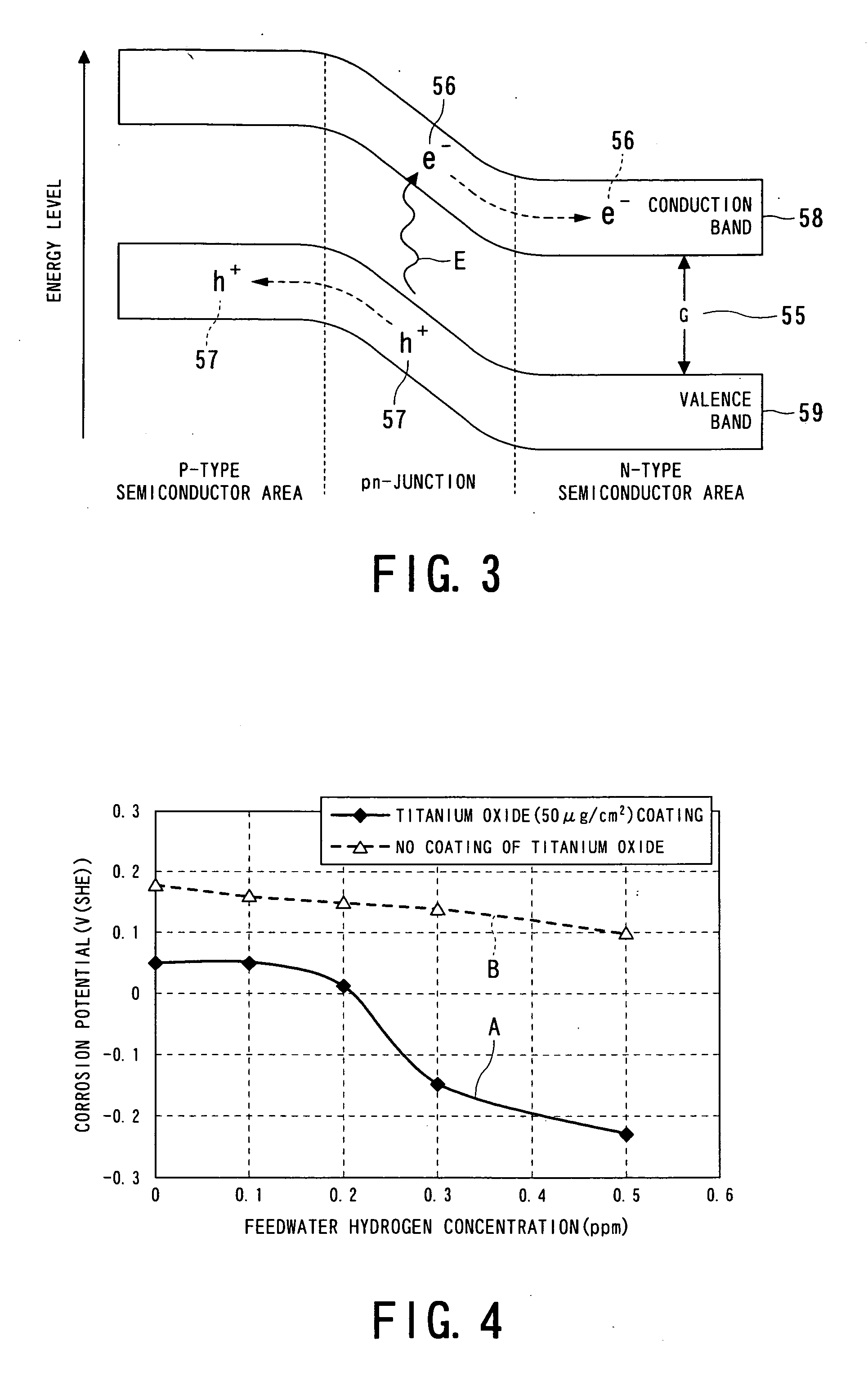
[0073] A first embodiment of the present invention will be described with reference to FIGS. 2 to 4.

[0074] In the first embodiment, the austenitic stainless steel widely used in the reactor structural materials of the reactor primary cooling system 45 and the cooling water circulation system 12 of the nuclear power plant 10 is provided with corrosion-resistant oxide films.

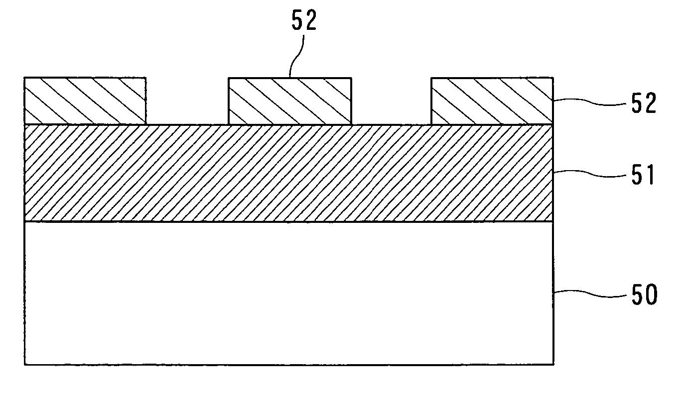
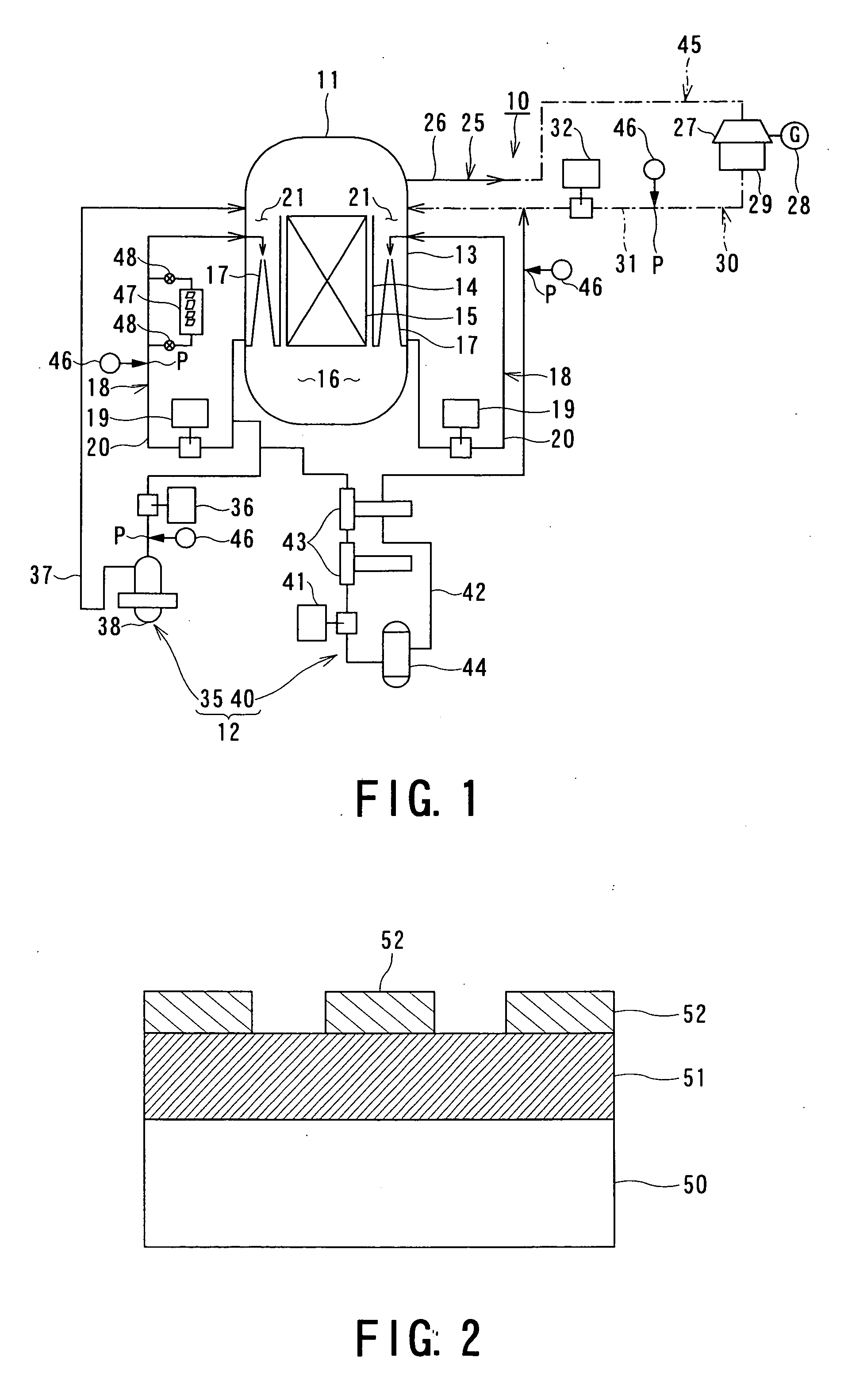
[0075]FIG. 2 is a schematic diagram showing a surface of a metal component having a corrosion-resistant coating on the surface of SUS316L stainless steel, which is one example of the austenitic stainless steel.

[0076] In this embodiment, a corrosion-resistant, corrosion-protective oxide film (film) 51 composed of an oxide, such as Fe3O4, having the properties of a P-type semiconductor is formed on a metal base material 50 composed of SUS316L stainless steel, and titanium oxide serving as a catalytic substance 52 having the properties of a N-type semiconductor is deposited on the oxide film 51.

[0077] The catalyti...

second embodiment

[0085] A second embodiment of the present invention will be described hereunder with reference to FIGS. 5 and 6.

[0086] In this second embodiment, the structures identical to those of the first embodiment are referred to by adding the same reference numerals and explanation thereof is omitted herein, and the effects identical to those of the first embodiment are also attained, which are not described to avoid redundancy.

[0087]FIG. 5 is a graph showing the influence of the particle diameter of the oxide having the properties of the P-type semiconductor deposited on the surface of the metal base material 50 on the corrosion potential V. The graph shows results of a case in which an Fe3O4 oxide film 51 is formed on the metal component made of austenitic stainless steel, SUS316L, and a case in which an NiO oxide film 51 is formed on the metal base material 50 made of stainless steel alloy, i.e., an Ni-based corrosion-resistant alloy, Alloy 600 (Inconel 600). A solid line C shows the co...

third embodiment

[0099]FIG. 9 is a graph related to a third embodiment of the present invention.

[0100] In the description of the third embodiment, the structures identical to those of the first embodiment are referred to by the same reference numerals to omit repeated explanation, and the effects identical to those of the first embodiment are also attained, but omitted in description to avoid redundancy.

[0101] The graph in FIG. 9 shows the corrosion potential characteristics observed from a test piece in which the metal base material 50 composed of SUS316L is coated with an Fe3O4 oxide film 51 having the properties of a P-type semiconductor and a thickness of 0.05 μm, and from a test piece in which the metal base material 50 composed of a Ni-based stainless steel alloy, i.e., Alloy 600, is coated with a NiO oxide film 51 having a thickness of 0.05 μm, while varying the amount of titanium oxide serving as the catalytic substance 52 deposited on the oxide film 51.

[0102] The graph shows that as the ...


PUM

PropertyMeasurementUnit
temperatureaaaaaaaaaa
average particle diameteraaaaaaaaaa
thicknessaaaaaaaaaa

Abstract

In a nuclear power plant, a corrosion-resistant oxide film on a surface of the metal component of a reactor structure is exposed to a high-temperature water, the corrosion-resistant oxide film containing an oxide having a property of a P-type semiconductor, and a catalytic substance having a property of an N-type semiconductor is deposited on the oxide film. The oxide film maintains the property of the P-type semiconductor.

Description

BACKGROUND OF THE INVENTION [0001] 1. Field of the Invention [0002] The present invention relates to a technology for suppressing corrosion of metal components, such as nuclear power plant's structural components, in contact with high-temperature water, and more particularly, relates to a nuclear power plant having a corrosion-resistant coating, a method of making such a corrosion-resistant coating and a method of operating the nuclear power plant. [0003] 2. Related Art [0004] Metal components exposed to high temperature environment are found in almost all of the modern industrial and commercial plants. For example, in the course of steam reforming in a hydrogen production chemical plant, the reaction is carried out at high temperatures and pressures. Inside a boiler or a metal pipe connected to the boiler, hot water and steam move or travel while causing corrosion. The conventional preventive measures against corrosion of metal components have involved use of expensive, special cor...

Claims


Application Information

Patent Timeline
Patent Type & Authority Applications(United States)
IPC IPC(8): G21C9/00
CPCG21C13/08G21C17/022G21C17/0225G21Y2002/103G21Y2004/10Y02E30/40Y02E30/30
Inventor OKAMURA, MASATOOOSATO, TETSUOYAMAMOTO, SEIJIYOTSUYANAGI, TADASUICHIKAWA, NAGAYOSHIYAMAZAKI, KENJITAKAGI, JUNICHIURATA, HIDEHIROSUZUKI, SHUNICHITAKAMORI, KENROSUZUKI, JUNICHI
Owner TOSHIBA ENERGY SYST & SOLUTIONS CORP
Why Eureka
Try Eureka