Nanoparticle production and corresponding structures

a nanoparticle and nanoparticle technology, applied in the direction of phosphorus compounds, vanadium oxides, zinc oxides/hydroxides, etc., can solve the problem of individual components integrated in the device shrinking in siz

Inactive Publication Date: 2006-07-06
NEOPHOTONICS CORP
View PDF99 Cites 58 Cited by
  • Summary
  • Abstract
  • Description
  • Claims
  • Application Information

AI Technical Summary

Benefits of technology

[0015] In additional aspects, the invention pertains to methods for producing product particles comprising an inorganic composition wherein the product particles have an average particle size of no more than about 75 nm. The methods comprise a step for producing the product particles at a rate of at least about 35 grams per hour.
[0016] In further aspects, the invention pertains to methods for producing product particles comprising an inorganic composition wherein the product particles have an average particle size of no more than about 500 nm. The particles have effectively no particles with a diameter greater than about 4 times the average particle size. The me

Problems solved by technology

Furthermore, the individual components inte

Method used


Image

  • Nanoparticle production and corresponding structures
  • Nanoparticle production and corresponding structures
  • Nanoparticle production and corresponding structures

Examples


example 1

Single Phase V2O5

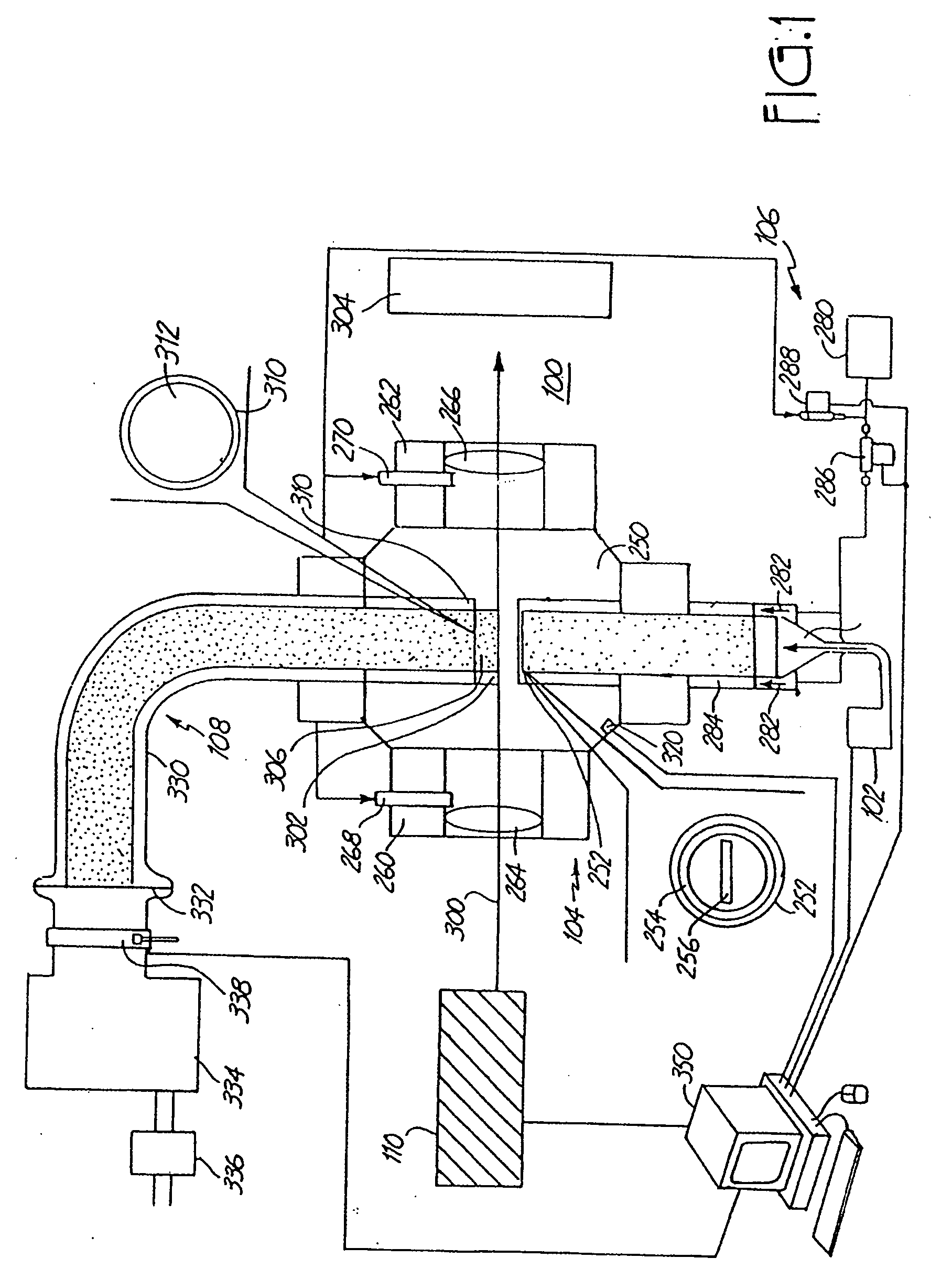
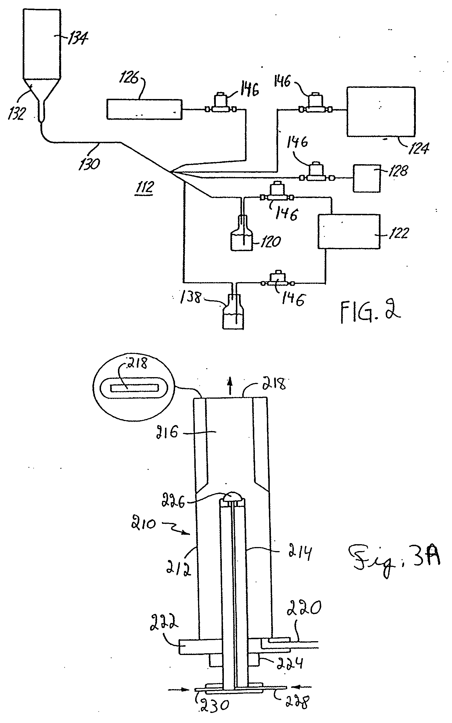
[0358] The synthesis of V2O5 described in this example was performed by laser pyrolysis. The VOCl3 (Strem Chemical, Inc., Newburyport, Mass.) precursor vapor is carried into the reaction chamber by bubbling Ar gas through the VOCl3 liquid stored in a container at room temperature. The reactant gas mixture containing VOCl3, Ar, O2 and C2H4 is introduced into the reactant gas nozzle for injection into the reactant chamber. The reactant gas nozzle had an opening with dimensions as specified in Table 1. C2H4 gas acts as a laser absorbing gas. Argon was used as an inert gas.

[0359] The synthesized vanadium oxide nanoscale particles can be directly handled in the air. The production rate was typically about 5-10 g / hour of nanoparticles. Based on the teachings herein both above and in this example, the particles described in this example can be produced with equivalent properties in appropriate apparatuses and at appropriate conditions at rates in the range(s) of at least...

example 2

Single Phase VO2

[0363] These particles were produced using a similar laser pyrolysis set up as described in Example 1. The reactant gas nozzle had dimensions ⅝ in× 1 / 16 in. For the production of VO2, C2H4 was bubbled through the VOCl3 liquid precursor at room temperature. Representative reaction conditions for the production of this material are described in Table 2.

TABLE 2PhaseVO2VO2VO1.27Crystal StructureMonoclinicMonoclinicTetragonalBattery Capacity (mAh / g)249118.4Pressure (Torr)320127200Argon - Win (sccm)700700700Argon - Sld. (slm)5.60.982.8Ethylene (sccm)460268402Carrier Gas (sccm)460(Ethyl.)676(Ar)402(Ethyl.)Oxygen (sccm)36200196Laser Output (watts)96220100

[0364] An x-ray diffractogram of representative product nanoparticles is shown in FIG. 30. Clear diffraction peaks corresponding to a monoclinic crystalline structure are visible. The identified structure from the diffractogram is almost identical to that of the corresponding bulk material, which has larger particle sizes...

example 3

Single Phase VO1.27

[0366] The experimental arrangement for the production of VO1.27 is the same as that described in Example 2. Representative conditions used to produce these particles are given in Table 2, above. Based on the teachings herein both above and in this example, the particles described in this example can be produced with equivalent properties in appropriate apparatuses and at appropriate conditions at rates in the range(s) of at least about 35 grams per hour and at higher rates described above.

[0367] The x-ray diffractogram for this material is shown in FIG. 34, and is characteristic of crystalline VO1.27 material.


PUM

PropertyMeasurementUnit
Fractionaaaaaaaaaa
Fractionaaaaaaaaaa
Fractionaaaaaaaaaa

Abstract

Methods are described that have the capability of producing submicron/nanoscale particles, in some embodiments dispersible, at high production rates. In some embodiments, the methods result in the production of particles with an average diameter less than about 75 nanometers that are produced at a rate of at least about 35 grams per hour. In other embodiments, the particles are highly uniform. These methods can be used to form particle collections and/or powder coatings. Powder coatings and corresponding methods are described based on the deposition of highly uniform submicron/nanoscale particles.

Description

CROSS REFERENCE TO RELATED APPLICATIONS [0001] This application is a divisional of copending U.S. patent application Ser. No. 10 / 195,851 to Bi et al., entitled “Nanoparticle-Based Powder Coatings And Corresponding Structures,” incorporated herein by reference, which is continuation-in-part of copending U.S. patent application Ser. No. 09 / 606,884 to Bi et al., entitled “Batteries With Electroactive Nanoparticles,” which is a continuation of U.S. patent application Ser. No. 09 / 333,099, now U.S. Pat. No. 6,130,007, which is a continuation of U.S. patent application Ser. No. 08 / 897,776 now U.S. Pat. No. 5,952,125; copending U.S. patent application Ser. No. 09 / 841,255 to Kambe et al., entitled “Abrasive Particles For Surface Polishing,” which is a continuation of U.S. patent application Ser. No. 08 / 961,735 now U.S. Pat. No. 6,290,735; copending U.S. patent application Ser. No. 09 / 558,266, now U.S. Pat. No. 6,890,624 to Kambe et al., entitled “Self-Assembled Structures”; copending U.S. pa...

Claims


Application Information

Patent Timeline
IPC IPC(8): B32B19/00B32B5/16
CPCB01J4/002Y10T428/2982B01J2219/1215B01J2219/1224B01J2219/1239B01J2219/1284B01J2219/1293B22F9/30B22F2999/00B82Y30/00C01B25/45C01B31/36C01B33/113C01G9/02C01G19/02C01G23/005C01G23/047C01G31/00C01G31/02C01G45/006C01G45/02C01G45/1242C01G49/00C01G49/04C01G49/06C01G51/00C01G51/42C01G53/42C01P2002/54C01P2002/72C01P2004/03C01P2004/04C01P2004/51C01P2004/52C01P2004/64C01P2006/12C01P2006/40B01J19/121B22F1/0018B22F1/0014B22F2202/11C01B32/956C01B32/977B22F1/054B22F1/052
Inventor BI, XIANGXINKAMBE, NOBUYUKIHORNE, CRAIG R.GARDNER, JAMES T.MOSSO, RONALD J.CHIRUVOLU, SHIVKUMARKUMAR, SUJEETMCGOVERN, WILLIAM E.DEMASCAREL, PIERRE J.LYNCH, ROBERT B.
Owner NEOPHOTONICS CORP
Why Eureka
Try Eureka