
SOFC assembly joint spacing

Active Publication Date: 2006-07-06
APTIV TECH LTD
View PDF18 Cites 18 Cited by
  • Summary
  • Abstract
  • Description
  • Claims
  • Application Information

AI Technical Summary

Benefits of technology

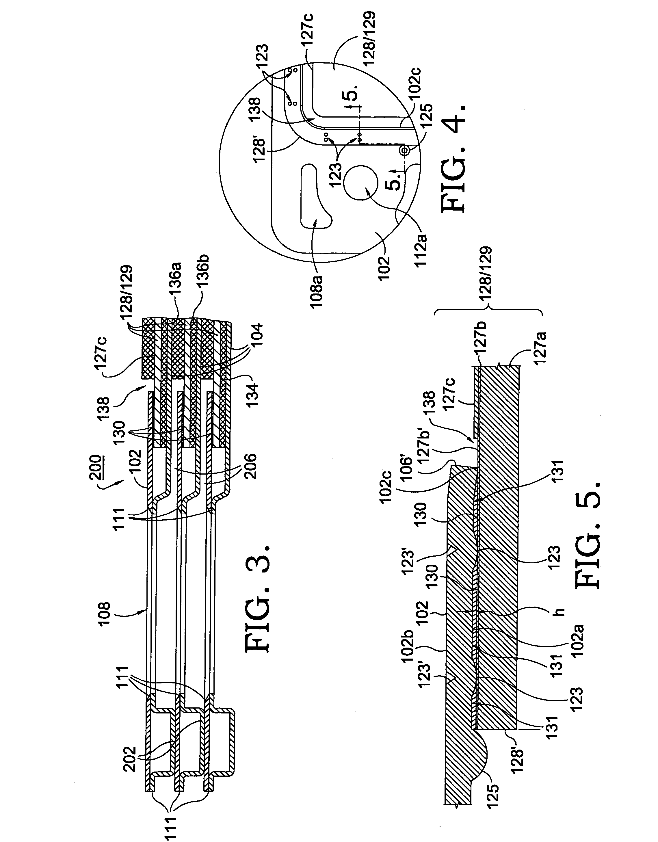
[0014] The uniform joint spacing provided by the dimples provide a number of advantages. For example, the precise amount of braze required to fill the spacing is easily quantifiable and may be dispensed in a uniform manner. This allows for a highly repeatable and robust automated assembly process, thereby reducing manufacturing costs. Material cost is even further reduce since there is no “squeezing out” of the braze which occurred in the prior art process. Also, the past problem of beads consuming some of the copper oxide is eliminated. Furthermore, since the dimples act as a hard stop, cell stack load forces will not reduce or eliminate the joint spacing as sometimes occurred in the prior art. In yet a further embodiment of the invention, a lip is formed in the mounting plate edge to prevent the braze from leaking onto the cathode surface which could cause a short circuit.

Problems solved by technology

Furthermore, since the dimples act as a hard stop, cell stack load forces will not reduce or eliminate the joint spacing as sometimes occurred in the prior art.

Method used


Image

  • SOFC assembly joint spacing
  • SOFC assembly joint spacing
  • SOFC assembly joint spacing

Examples


Embodiment Construction

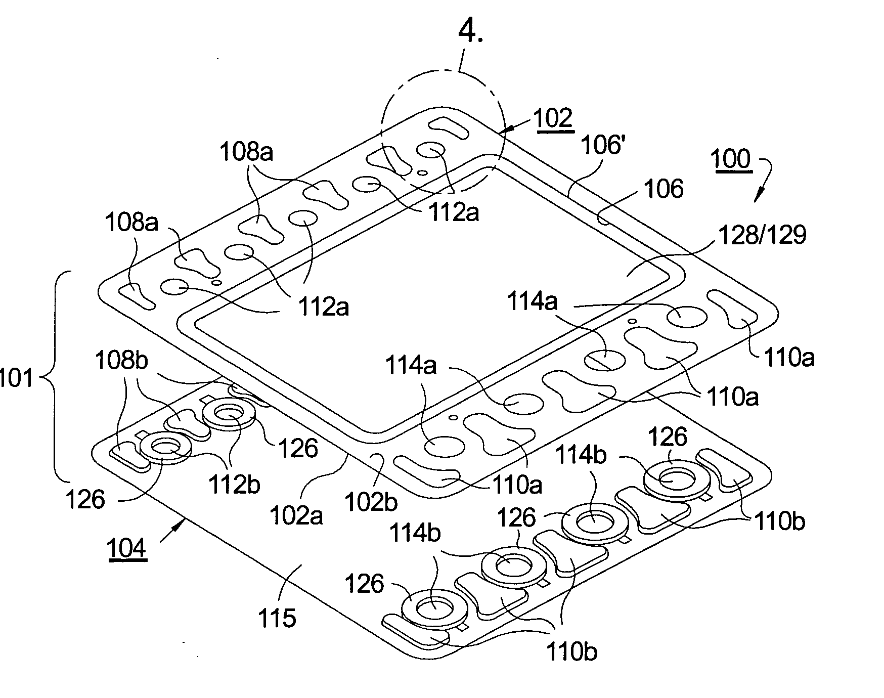
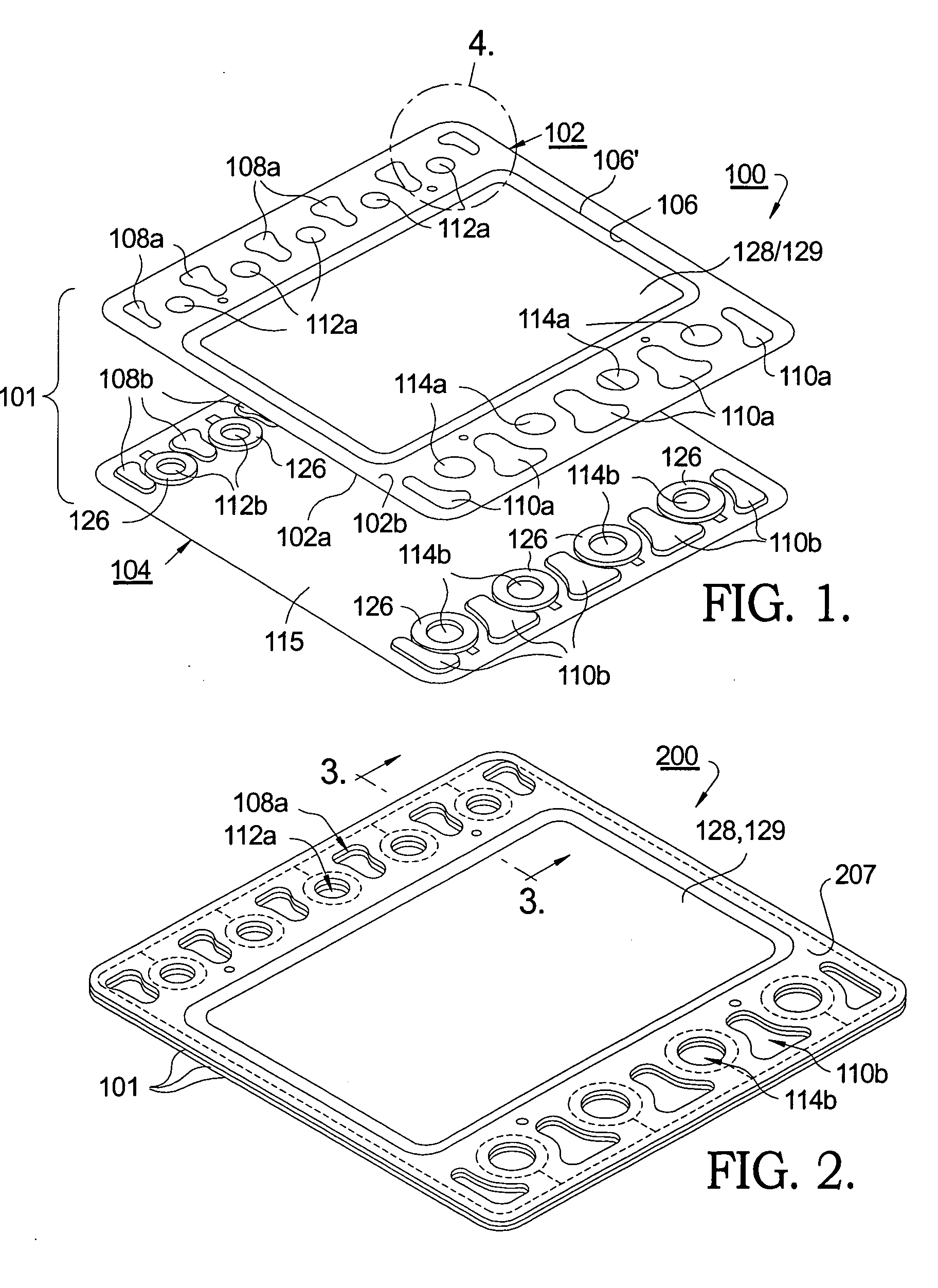
[0021] Referring to FIG. 1, a fuel cell cassette 100 in accordance with an embodiment of the invention includes a cassette housing 101 including a fuel cell mounting plate 102 and a separator plate 104. Mounting plate 102 includes a large central electrode opening 106 for receiving a fuel cell subassembly 128 as described below. Outboard of central electrode opening 106 are cathode air inlets 108a, cathode air outlets 110a, fuel gas inlets 112a and fuel gas outlets 114a. Separator plate 104 is provided with similar and mating air and fuel openings 108b, 110b, 112b, and 114b, respectively. Separator plate 104 is formed as a shallow tray 115 such that a cavity is created between plates 102, 104 for receiving fuel cell components and fuel gas as described below. Preferably, the mounting and separator plates are formed as by stamping or drawing from thin sheet stock (about 0.1 to 1.0 mm) of a ferretic stainless steel, such as Crofer 22, although other materials such as austenitic stainl...


PUM

PropertyMeasurementUnit
Heightaaaaaaaaaa
Heightaaaaaaaaaa
Heightaaaaaaaaaa

Abstract

A textured surface is formed on at least one of a fuel cell mounting plate or fuel cell subassembly to define a joint spacing between these two components. In a preferred embodiment, the textured surface comprises a plurality of dimples coined or otherwise formed in the metal mounting plate. The joint spacing improves the manufacturing and assembly process of the fuel cell cassettes through precise application and control of the brazing process which improves the braze joint strength while reducing material cost.

Description

GOVERNMENT STATEMENT [0001] This invention was made with United States Government support under Government Contract / Purchase Order No. DE-FC26-02NT41246. The Government has certain rights in this invention.RELATIONSHIP TO OTHER APPLICATIONS AND PATENTS [0002] This application is a continuation-in-part of previously filed application Ser. No. 11 / 027,095 filed Dec. 30, 2004 and entitled “MODULAR FUEL CELL CASSETTE FOR FORMING A SOLID-OXIDE FUEL CELL STACK”. TECHNICAL FIELD [0003] The present invention relates to fuel cells; more particularly, to solid-oxide fuel cells; and most particularly, to joint seal formation between components of a fuel cell stack. BACKGROUND OF THE INVENTION [0004] Fuel cells for combining hydrogen and oxygen to produce electricity are well known. A known class of fuel cells includes a solid-oxide electrolyte layer through which oxygen anions migrate; such fuel cells are referred to in the art as “solid-oxide” fuel cells (SOFCs). [0005] In some applications, f...

Claims


Application Information

Patent Timeline
IPC IPC(8): H01M8/02H01M8/12
CPCB23K1/0008B23K1/008B23K2201/18B23K2203/04H01M8/0232H01M8/0247H01M8/0273H01M8/0276H01M8/0282H01M8/0297H01M8/2425H01M8/247H01M2008/1293Y02E60/50Y02E60/525B23K2101/18B23K2103/05Y02P70/50H01M8/0271
Inventor REISDORF, GARY F.HALTINER, KARL J. JR.
Owner APTIV TECH LTD
Learn More