[0010] The present invention has been made in view of the above problem. It is an object of the present invention to provide a spherical bearing manufacturing method which allows in a simple manner smooth rotation of the ball portion relative to the outside member after the casting and which makes it possible to completely eliminate the gap between the ball portion and the resin liner, making it possible to maintain a satisfactory slide contact between the ball portion and the resin liner for a long period of time.
[0011] To achieve the above object, the present invention provides aspherical bearing manufacturing method in which a
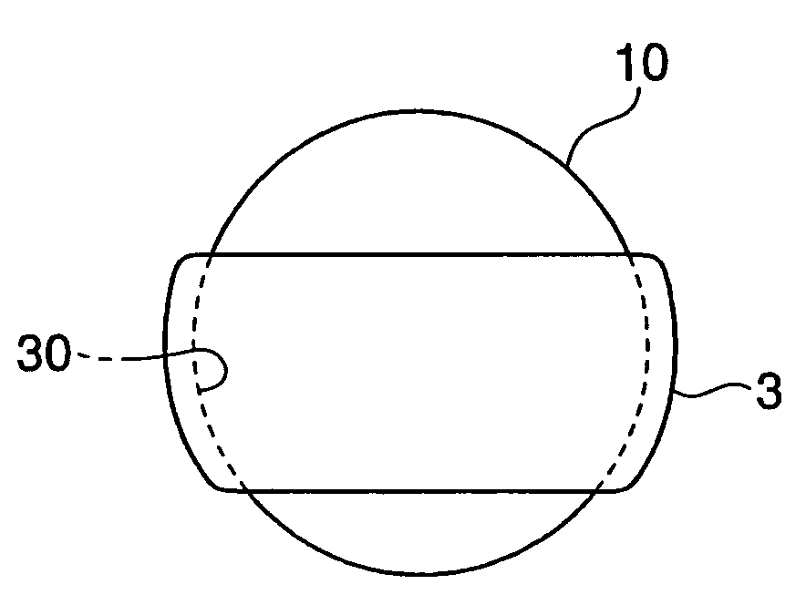
metal ball portion constituting the inside member is inserted into a mold as a core before performing injection molding to form a resin liner covering the ball portion. This resin liner is molded by using the ball portion as the core, so that no gap exists between the resin liner and the spherical surface of the ball portion, and the spherical surface of the ball portion is transferred as it is to the resin liner. Thus, by using a bearing
steel ball of high
sphericity as the ball portion, it is possible to form a satisfactory mirror-surface-like slide surface on the resin liner, making it possible to bring this slide surface into
close contact with the ball portion. Further, by molding the resin liner so as to cover the
equator of the ball portion, it is possible to prevent the resin liner after molding from being separated from the ball portion. Accordingly it is possible to hand the ball portion and the resin liner as an integral unit in the subsequent manufacturing processes.
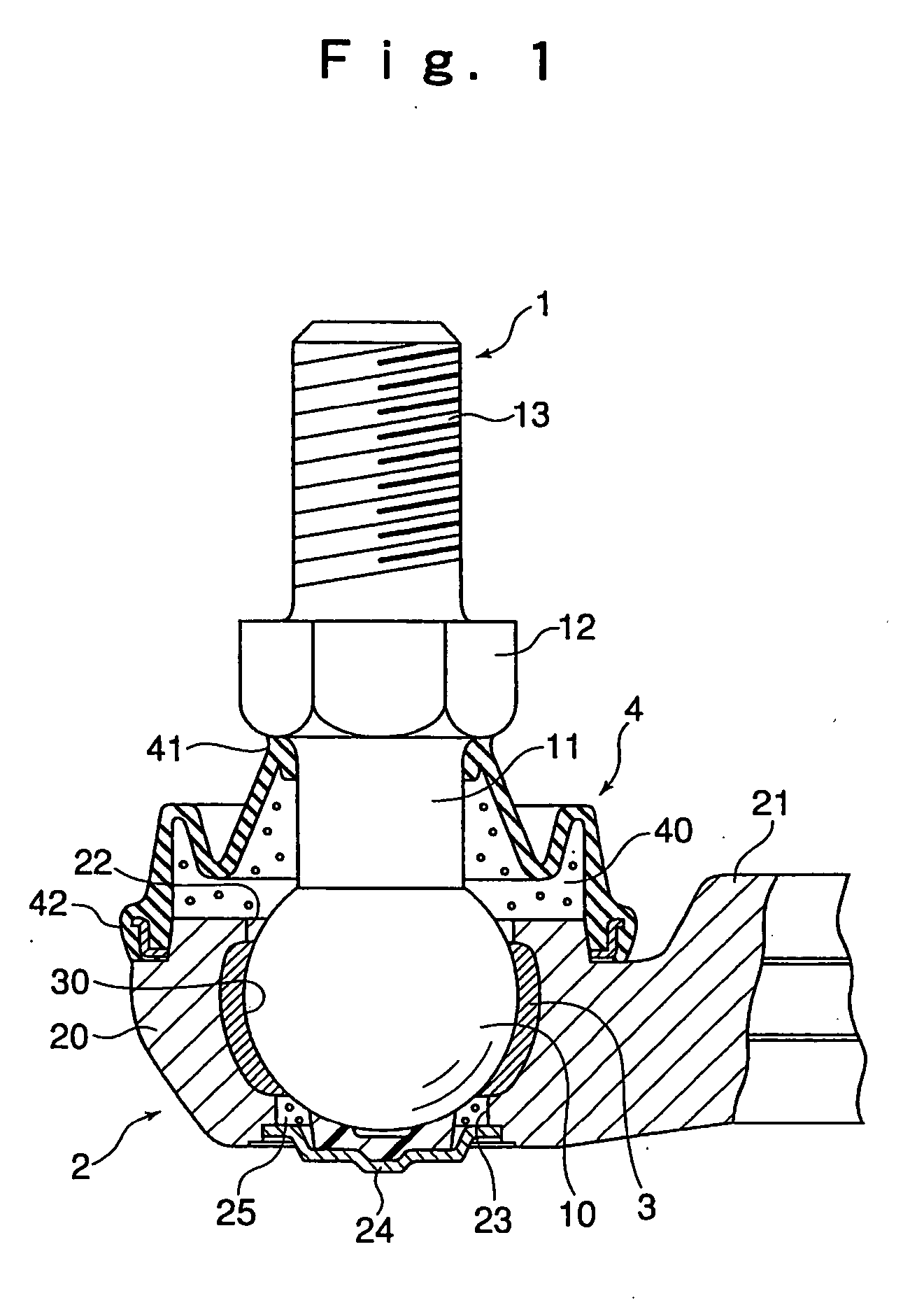
[0012] Next, the ball portion with the resin liner attached thereto is inserted into the mold as a core, and the outside member covering the resin liner from outside is cast. From the view point of enhancing the dimensional accuracy of the spherical bearing manufactured, the casting is preferably
squeeze casting; further, from the viewpoint of
mass production, die-casting, which allows setting of the
cycle time short, is preferable. Examples of the
alloy that can be used for casting include
zinc alloy, aluminum
alloy,
magnesium alloy, and
titanium alloy; in the case of a spherical bearing used in a leg part such as an automotive suspension structure, it is desirable to use an aluminum alloy,
magnesium alloy, etc. from the viewpoint of a reduction in weight.
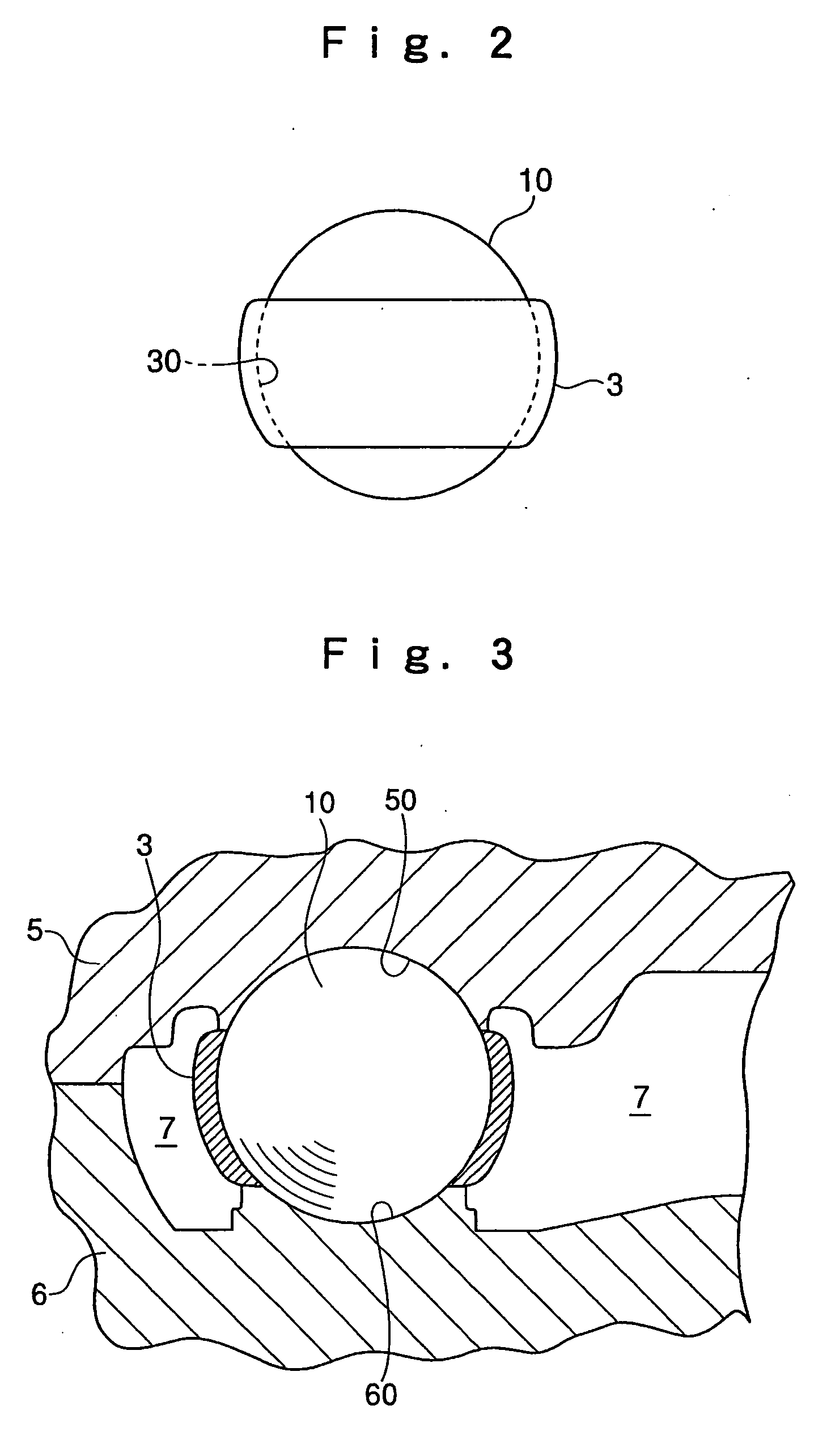
[0014] Thus, in the method of the present invention, after the casting of the outside member, the resin liner covering the ball portion is heated through the ball portion of the inside member. The resin liner encloses and is in
close contact with the ball portion, so that, when the ball portion is heated, the
heat energy is conducted to the resin liner, and the resin liner is also heated to some degree. When, at this time, the resin liner undergoes temperature rise, and is heated to a temperature near the
glass transition temperature Tg, the
mechanical strength of the resin liner, such as the bending modulus, is gradually reduced, so that the resin liner becomes easily deformable in conformity with the size of the ball portion; when the resin liner is cooled after this heating, the tightening force of the resin liner with respect to the ball portion is reduced. Further, since the heated ball portion expands, it also occurs that the ball portion expands the resin liner, which also contributes to the tendency of the tightening force of the resin liner to be reduced after the cooling of the ball portion.
[0015] Accordingly, by thus heating the resin liner through the ball portion after the casting of the outside member, it is possible to mitigate the force with which the resin liner tightens the ball portion, enabling the ball portion to smoothly rotate relative to the resin liner. Thus, in this method, the ball portion becomes rotatable relative to the resin liner. However, since no gap is formed between the two, it is possible to completely eliminate rattling of the ball portion with respect to the outside member, thus making it possible to effect transmission of load and transmission of motion with high accuracy between the outside member and the inside member even in the case of a long-term use. Further, since it is possible to realize smooth rotation of the ball portion solely by heating the ball portion after the casting of the outside member, the method can be executed very easily, making it possible to easily cope with
automation of each manufacturing process and
mass production.
[0016] While, in heating the resin liner through the ball portion in the final process, it is only necessary to heat the ball portion, it is also possible to apply an external force to the ball portion, crushing the ball portion within an elastic deformation range. By thus pressurizing the ball portion simultaneously with the heating of the resin liner and crushing the ball portion, the elastically deformed ball acts so as to pressurize the resin liner toward the outside member, so that the effect of expanding the resin liner is enhanced, making it possible to more effectively reduce the force with which the ball portion is tightened by the resin liner.

