Liquid fuel recirculation system and method

Inactive Publication Date: 2006-07-13
GENERAL ELECTRIC CO
View PDF9 Cites 25 Cited by
  • Summary
  • Abstract
  • Description
  • Claims
  • Application Information

AI Technical Summary

Benefits of technology

[0012] Exemplary embodiments of the present invention provide a recirculation system for circulating distillate during gas fuel operation so as to reduce or eliminate distillate carbon formation. Adding a recirculation system embodying the invention offers multiple benefits. First, it keeps the distillate's temperature below the carbon formation limit

Problems solved by technology

Because gas fuel is used as the primary fuel, liquid fuel systems may remain inoperable for relatively long periods.
If the flow dividers are not exercised regularly, they become vulnerable to having their gears bind.
Reasons for not periodically running the liquid fuel systems may include reliability issues, emissions concerns and an unwillingness to decrease loads simply to transfer fuels, especially when power is trading favorably.
Existing F-Class gas turbines that have dual fuel capacity (gas fuel as primary and distillate as backup) are susceptible to carbon deposits forming in the liquid fue

Method used


Image

  • Liquid fuel recirculation system and method
  • Liquid fuel recirculation system and method
  • Liquid fuel recirculation system and method

Examples


Embodiment Construction

[0021] As noted above, hot temperatures in the turbine compartment lead to carbon formation in stagnant fuel lines. Carbon formation results in valve malfunctioning and / or nozzle plugging, which in turn causes excessive trips during fuel transfers, liquid fuel startups and liquid fuel operations. Fuel data indicates that if the tubing wall temperatures of the fuel oil system are held below 200° F. then carbon formation will be minimized.

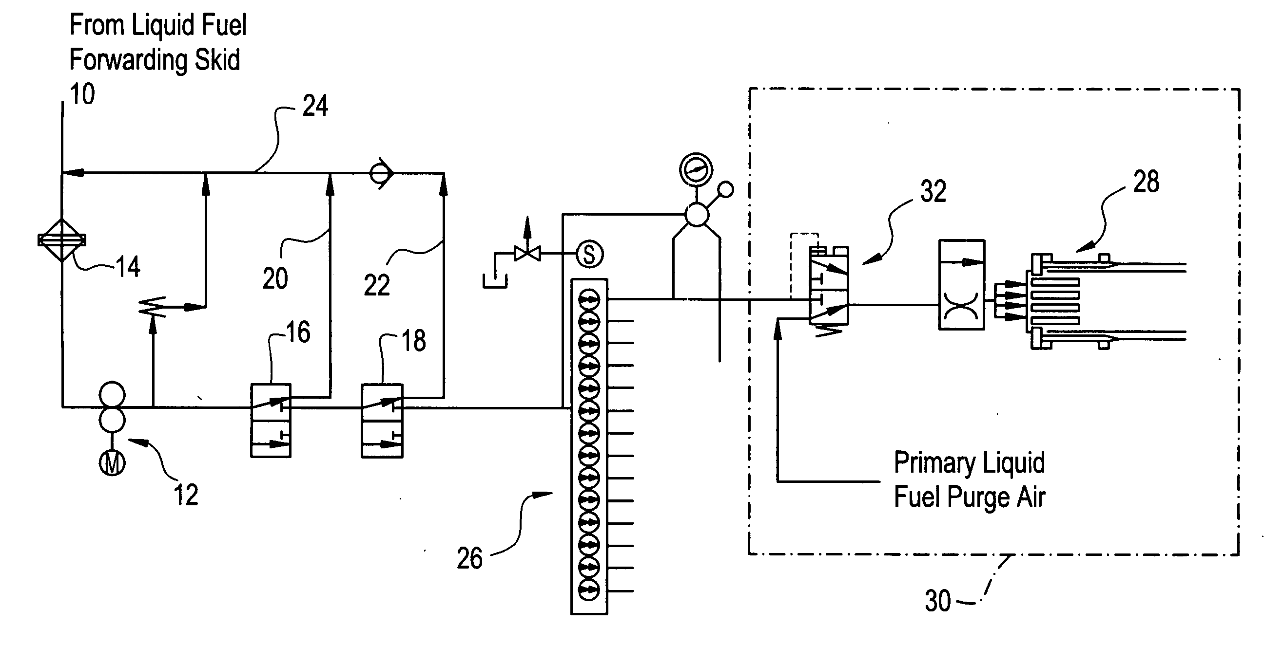
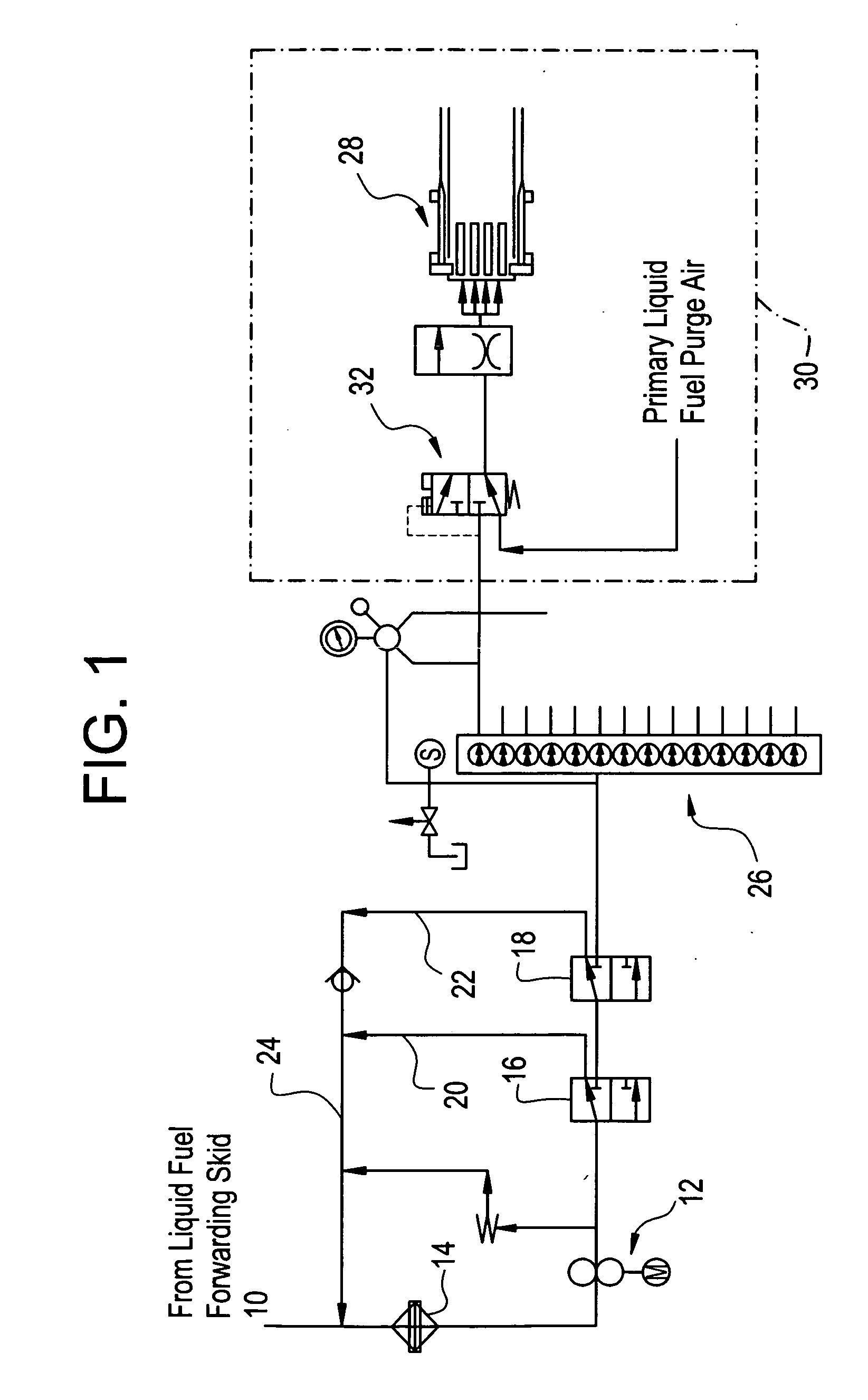
[0022] As will be described herein below, the liquid fuel recirculation system embodying the invention provides a number of functions. First, the system keeps the liquid fuel wetted wall temperature below 200° F. The system further maintains continuous operation of the system and prevents the settling of air and water that causes corrosion and subsequent binding of the gears in the flow divider. The fuel recirculation system also minimizes air entrapment / infiltration into the system.

[0023] As noted above, FIG. 1 is a schematic illustration of an ex...


PUM


Abstract

A recirculation system for circulating distillate during gas fuel operation so as to reduce or eliminate distillate carbon formation. The recirculation system keeps the distillate's temperature below the carbon formation limit by circulating the distillate back to a storage tank to cool the distillate due to a volume of the storage tank compared to the volume of the recirculation system. The recirculating flow also exercises the flow dividers' gears without having to perform fuel transfers. Further, the system evacuates air from the liquid fuel lines to further decrease the likelihood of carbonaceous residue forming on any interior surfaces that are actually exposed to distillate.

Description

BACKGROUND OF THE INVENTION [0001] In dual-fuel gas turbines, the turbine operates by burning either a gaseous fuel or a liquid fuel, the latter fuel typically being distillate oil. These gas turbines have fuel supply systems for both liquid and gas fuels. The gas turbines generally do not burn both gas and liquid fuels at the same time. Rather, when the gas turbine burns liquid fuel, the gas fuel supply is turned off, and when the gas turbine burns gaseous fuel, the liquid fuel supply is turned off. [0002] In an exemplary industrial gas turbine, the combustor may have an array of combustion cans, each of which has a liquid fuel nozzle and a gas fuel nozzle. In the combustion can arrangement, combustion is initiated within the combustion cans at a point slightly downstream of the nozzles. Air from the compressor flows around and through the combustion cans to provide oxygen for combustion. Water injection nozzles are arranged within the combustor to introduce water to the combustion...

Claims


Application Information

Patent Timeline
IPC IPC(8): F02C7/22
CPCF02C7/22
Inventor SMITH, DAVID WILLIAMBACKMAN, STEVE WILLIAMKUNKLE, KEVIN LEECHRISFIELD, DAVID JOHN
Owner GENERAL ELECTRIC CO
Why Eureka
Try Eureka