
Protecting layer, composite for forming the same, method of forming the protecting layer, plasma display panel comprising the protecting layer

a technology of protecting layer and composite, which is applied in the manufacture of electrode systems, cold cathode manufacturing, and discharge tube/lamp manufacturing. it can solve the problems of reducing the starting voltage of the discharge, the dielectric can be damaged by sputtering etching, and the difficulty of controlling the discharge current, so as to reduce the dependency of the discharge delay time on temperature, the effect of increasing the sputtering resistance and reducing the discharge delay tim

Inactive Publication Date: 2006-07-13
SAMSUNG SDI CO LTD
View PDF13 Cites 4 Cited by
  • Summary
  • Abstract
  • Description
  • Claims
  • Application Information

AI Technical Summary

Benefits of technology

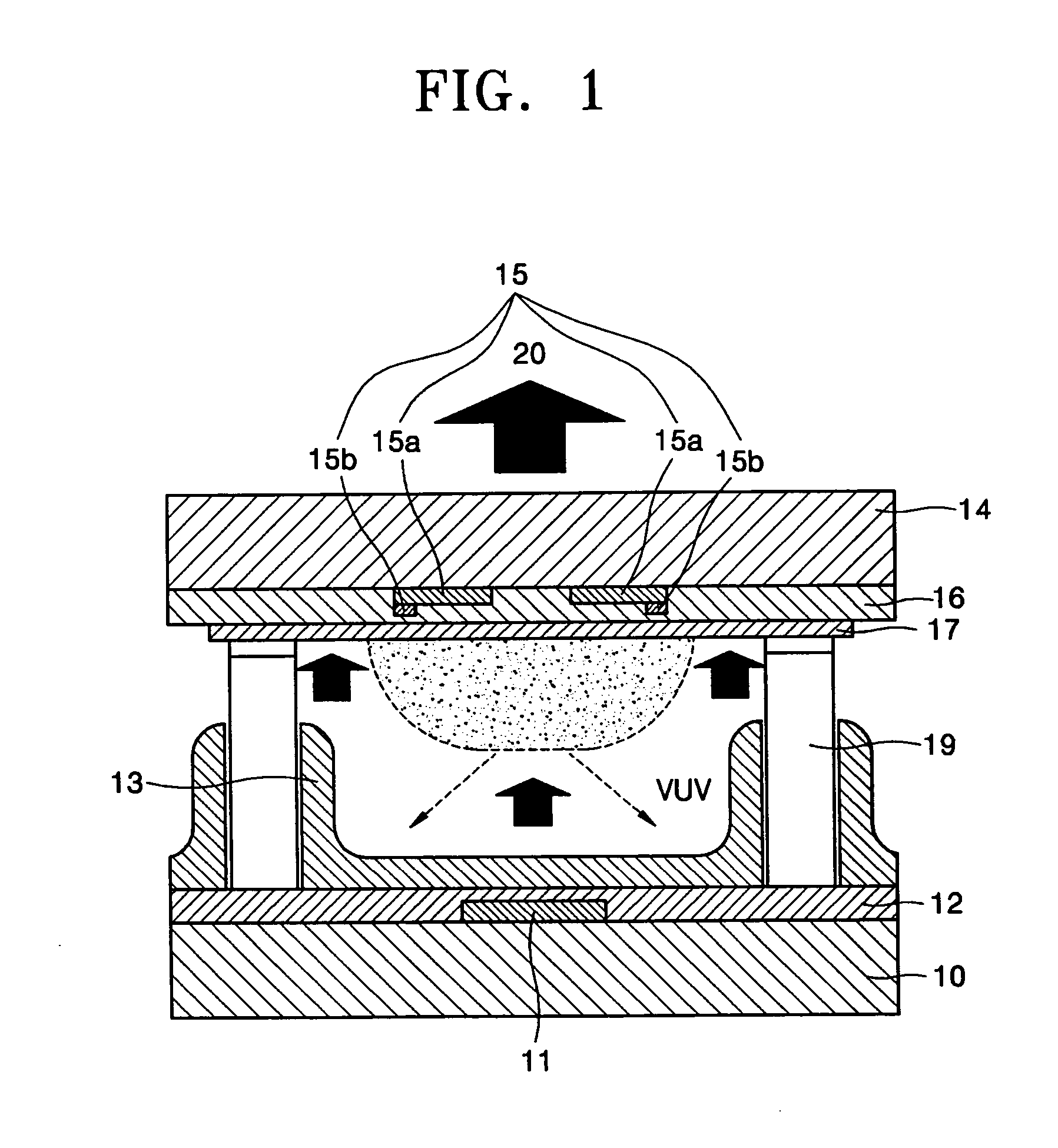
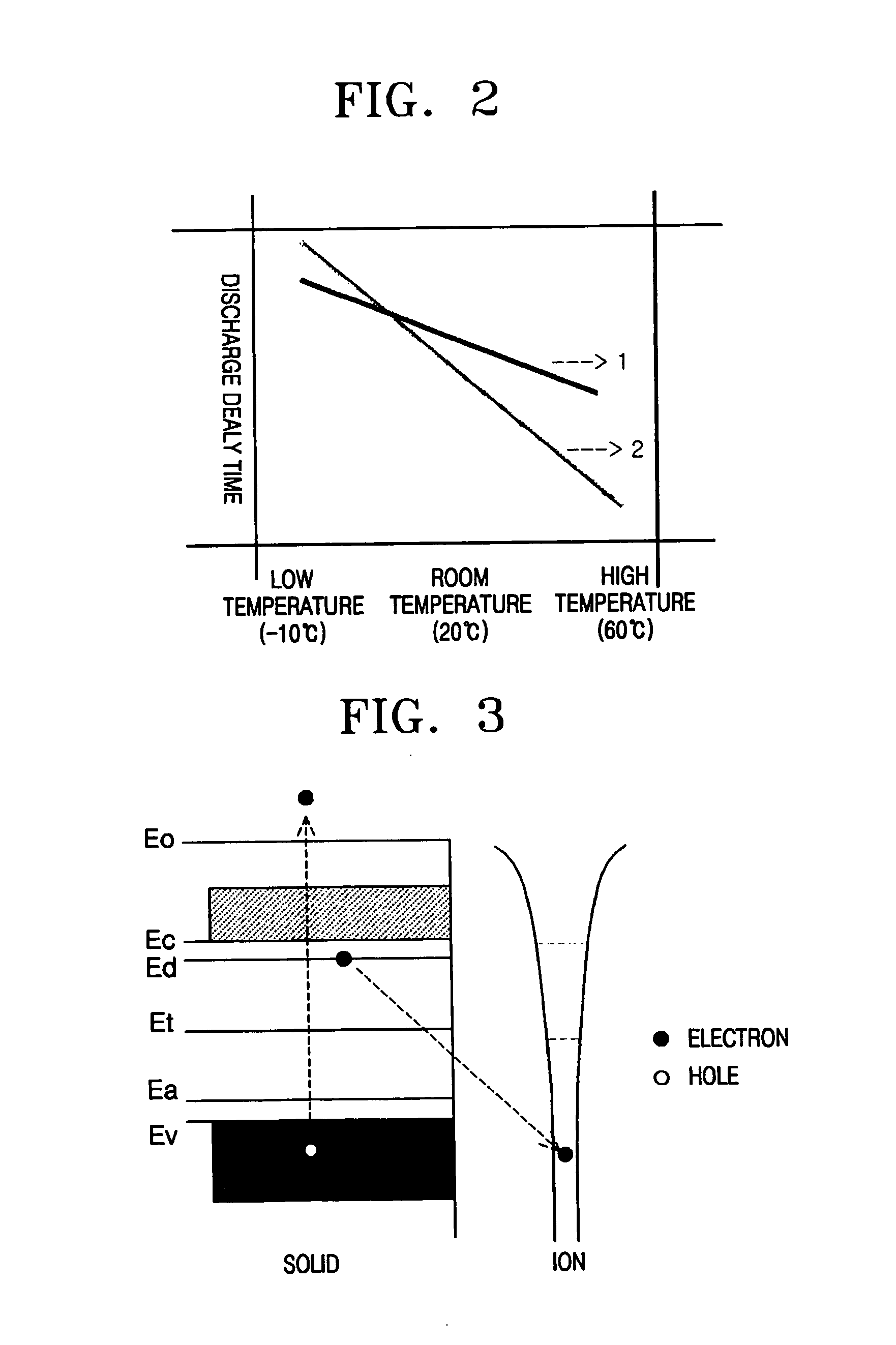
[0017] According to a protecting layer according to the present invention, the discharge delay time is decreased, dependency of the discharge delay time on temperature is decreased, and sputtering resistance can be increased. Thus, a PDP of long lifetime and high brightness can be obtained.

Problems solved by technology

However, when there is the electrode only, it is difficult to control a discharged current, and when there is the dielectric and the electrode only, the dielectric can be damaged by sputtering etching.
Second, the discharge starting voltage decreases.
However, the use of a conventional protecting layer of a PDP fails to decrease the discharge starting voltage and the discharge delay time to a desired level.

Method used


Image

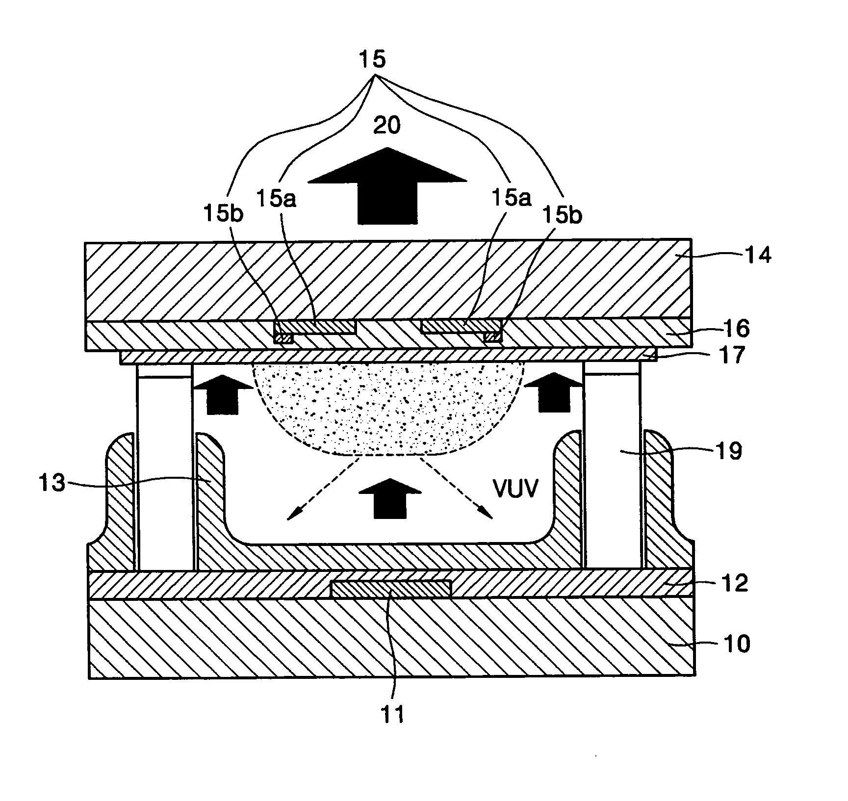
  • Protecting layer, composite for forming the same, method of forming the protecting layer, plasma display panel comprising the protecting layer
  • Protecting layer, composite for forming the same, method of forming the protecting layer, plasma display panel comprising the protecting layer
  • Protecting layer, composite for forming the same, method of forming the protecting layer, plasma display panel comprising the protecting layer

Examples


manufacture example 1

[0076] Manufacture of Discharge Cell

[0077] MgO and Cu(NO3)2, of which amounts were controlled such that the amount of Cu was 5.0×10⁻⁵ g based on 1 g of the magnesium oxide, were mixed by stirring for 5 hours or greater in a mixer to produce a homogeneous mixture. MgF2 as a flux was added to the mixture, and the result was stirred and heat treated at 900° C. for 5 hours in a melting pot. The heat treated result was compressively molded in a form of a pellet, and heat treated at 1650° C. for 3 hours. As a result, a composite for forming a protecting layer, in which the amount of Cu was 5.0×10⁻⁵ g based on 1 g of the magnesium oxide, was prepared.

[0078] Meanwhile, an Ag electrode with a predetermined pattern was formed on a glass (PD 200 Glass) with a size of 22.5×35×3 mm. Subsequently, the Ag electrode was covered with a PbO glass to form a PbO dielectric layer with a thickness of about 30 μm to 40 μm. The composite for forming a protecting layer was deposited on the PbO dielectric ...

manufacture example 2

[0085] A discharge cell was produced in the same manner as in Manufacture Example 1, except that MgO and Cu(NO3)2, of which amounts were controlled such that the amount of Cu was 1.0×10⁻⁴ g based on 1 g of magnesium oxide, were mixed to form a composite for forming a protecting layer, and ultimately, a protecting layer, of which the amount of Cu was 1.0×10⁻⁴ g based on 1 g of the magnesium oxide (that is, the amount of Cu was 100 ppm based on 1 g of the magnesium oxide), was obtained. The discharge cell will be referred to Sample 2.

manufacture example 3

[0086] A discharge cell was produced in the same manner as in Manufacture Example 1, except that MgO and Cu(NO3)2, of which amounts were controlled such that the amount of Cu was 2.0×10⁻⁴ g based on 1 g of magnesium oxide, were mixed to form a composite for forming a protecting layer, and ultimately, a protecting layer, of which the amount of Cu was 2.0×10⁻⁴ g based on 1 g of the magnesium oxide (that is, the amount of Cu was 200 ppm based on 1 g of the magnesium oxide), was obtained. The discharge cell will be referred to Sample 3.


PUM

PropertyMeasurementUnit
weightaaaaaaaaaa
temperatureaaaaaaaaaa

Abstract

A protecting layer is formed of a magnesium oxide and at least one additional component selected from the group consisting of a copper component selected from copper and a copper oxide, a nickel component selected from nickel and a nickel oxide, a cobalt component selected from cobalt and a cobalt oxide, and an iron component selected from iron and an iron oxide; a composite for forming the protecting layer; a method of forming the protecting layer; and a plasma display panel including the protecting layer. The protecting layer, which is used in a PDP, protects an electrode and a dielectric layer from a plasma ion generated by a gaseous mixture of Ne and Xe, or He, Ne, and Xe, and discharge delay time and dependency of the discharge delay time on temperature can be decreased and sputtering resistance can be increased.

Description

CROSS-REFERENCE TO RELATED PATENT APPLICATIONS AND CLAIM OF PRIORITY [0001] This application claims the benefit of Korean Patent Application No. 10-2005-0002430, filed on 11 Jan. 2005, in the Korean Intellectual Property Office, the disclosure of which is incorporated herein in its entirety by reference. BACKGROUND OF THE INVENTION [0002] 1. Field of the Invention [0003] The present invention relates to a protecting layer, a composite for forming the same, a method of forming the protecting layer, and a plasma display panel including the protecting layer, and more particularly, to a protecting layer which is formed of a magnesium oxide, and at least one additional component selected from the group consisting of a copper component, a nickel component, a cobalt component, and an iron component in order to improve discharge delay time and sputtering resistance; a composite for forming the protecting layer; a method of forming the protecting layer; and a plasma display panel including t...

Claims


Application Information

Patent Timeline
Patent Type & Authority Applications(United States)
IPC IPC(8): C04B35/04H01J17/00H01J9/24C01G3/00C01G49/00C01G51/00C01G53/00H01J9/02H01J11/22H01J11/34H01J11/40
CPCC04B35/04C04B35/653C04B2235/3272C04B2235/3275C04B2235/3279C04B2235/3281C04B2235/443C04B2235/445C23C30/00H01J11/12H01J11/40
Inventor LEE, MIN-SUKCHOI, JONG-SEOKIM, SUK-KIKIM, JAE-HYUKSUH, SOON-SUNG
Owner SAMSUNG SDI CO LTD
Learn More