Viscometric flowmeter

a flowmeter and flow rate technology, applied in the field of liquid chromatography, high-performance liquid chromatography, and preparative chromatography, can solve the problems of inability to accurately measure flow rate, momentary pressure drop, etc., to achieve faster response, improve accuracy, and improve the effect of dynamic rang

Inactive Publication Date: 2006-07-20
BEST JOHN W
View PDF31 Cites 16 Cited by
  • Summary
  • Abstract
  • Description
  • Claims
  • Application Information

AI Technical Summary

Benefits of technology

[0040] The present invention achieves superior performance, including operation across a wide range of pressures and temperatures, higher dynamic range, faster response and higher reliability over a wide range of flow rates, e.g. tens of nanoliters per minute (nL / min) to liters per minute (L / m).

Problems solved by technology

It follows in practice that most flow consistency and accuracy issues originate because of the fundamental character of the pump.
The lack of additional fluid to compensate for the normal loss of fluid through the LC column causes a momentary pressure drop.
If the pump or system does not specifically and correctly compensate for the required pre-compression, the flow rate will be incorrect.
Therefore, an LC system that is properly pre-compensated for a new column will suffer degradation in elution consistency if the pre-compensation is not adjusted with regard to the required flow vs. pressure characteristic of the aging column.
The problem lies in attempting to decrease flow rate by simply slowing the rotation of the pump's cam.
A typical reduction in flow rate will result in a longer period of time in which pressure decay will occur.
This is true of pumps using mechanically connected cams (driven by a single motor) to drive the pistons, because the refill stroke cannot be altered without affecting the opposing piston's fill stroke.
The net effect of the foregoing problem is that eluents do not arrive at the output of the LC column at consistent times, and there is a possibility of the eluents themselves being misclassified.
A serious fundamental problem with this approach, however, is that the backpressure of the column itself varies over time, typically increasing as the column ages.
As the column backpressure changes, it is necessary that a corresponding change occur in the regulating output of the T, otherwise column flow will be adversely affected.
Even in the presence of either automatic or manual adjustment of the backpressure regulation means, the overall backpressure encountered by the pump changes, potentially shifting its operating point into a pressure range that is undesirable.
As of yet, there is no economical means to characterize column backpressure with regard to flow rate; or to measure the column flow rate on the high pressure side of the column when using a conventional cam-driven pump; or to quantify flow deviation as a function of time and pump operating pressure; or to alert a user as to the presence of adverse operating conditions; or to collect pressure and flow data from an independent device which can be used to validate system performance in the absence of any anomaly.
None of these methods are viable below sub-mL / minute (e.g. μL / m and nL / m) ranges of flows.
Furthermore, none of the methods are suitable to advance the state-of the-art in LC or HPLC because they do not have adequately fast sampling rates to measure short term flow fluctuations.
The primary disadvantage of this method is that it does not allow adequate time resolution to detect or quantify sufficiently short term deviations in flow.
Such deviations typically result from piston pumps and incorrect compensation for compressibility of the liquid being pumped, as has been described hereinabove.
This “thermal gradient” approach does allow the measurement of short term deviation of flow, but disadvantageously does not allow either a wide dynamic range or optimum insertion of the flowmeter in the flow path due to inability of the thermal gradient type flowmeter to withstand high operating pressures greater than a few hundred PSI.
However, the drawbacks to the traditional thermal sensing flowmeters illustrate the need for alternatives or improvements in controlling flow deviation and pre-compression in a hydraulics system.

Method used


Image

  • Viscometric flowmeter
  • Viscometric flowmeter
  • Viscometric flowmeter

Examples


Embodiment Construction

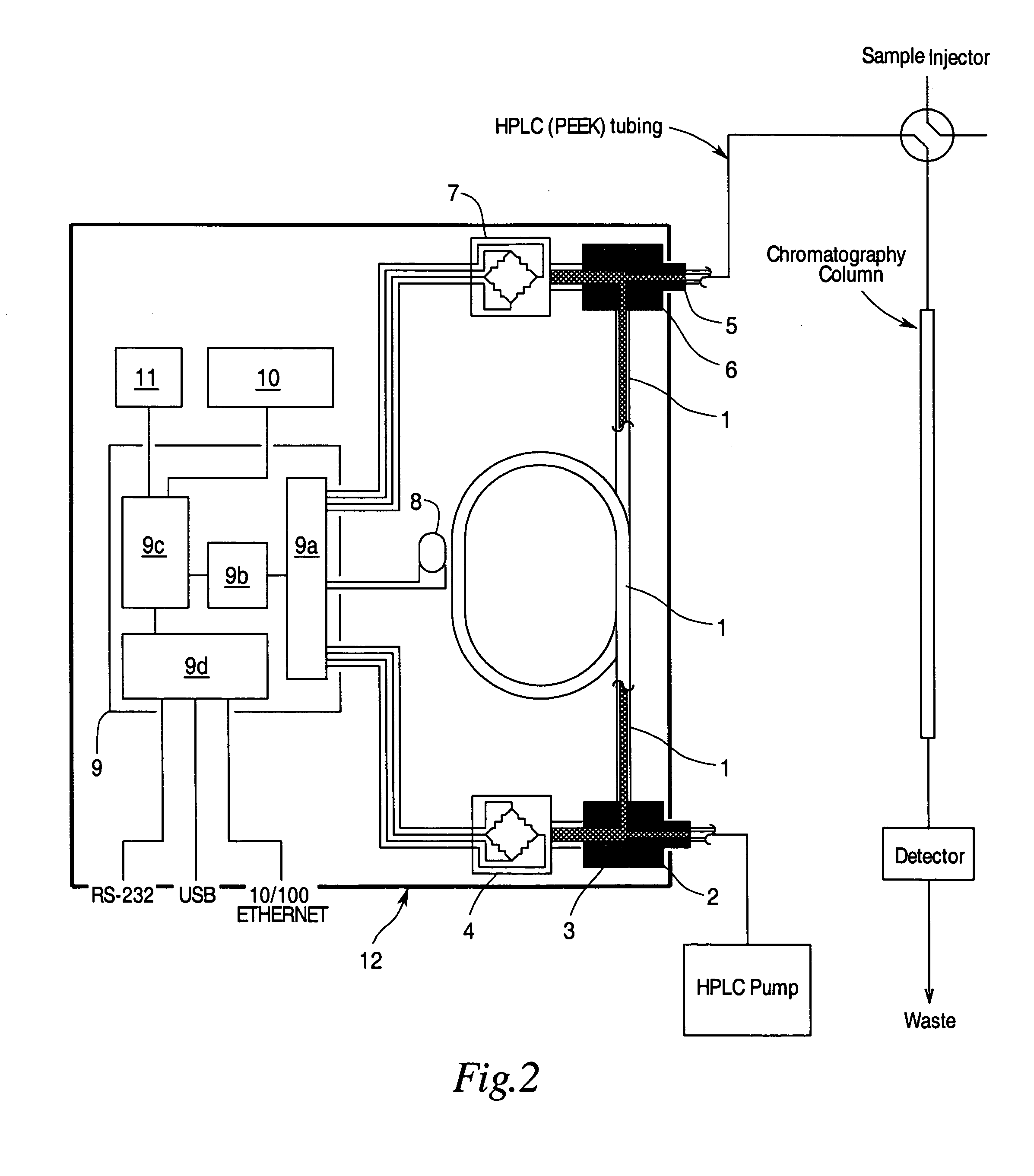
[0048] The present invention comprises a system and a method for reproducibly and accurately measuring the parameters that affect the flow of liquids in pressure-driven pumping systems. By way of example, the system can be used to determine pressure, temperature, flow, and other parameters in liquid chromatography (LC), which includes preparative chromatography and high performance liquid chromatography (HPLC) systems. Pressures in HPLC can be very high (up to 20,000 PSI) and flow rates can be extremely low (below μL / min) and thus difficult to measure accurately and control under the best of conditions. The system is such that it can advantageously be used to provide data for feedback and control of pumps or other devices which directly impact the fluid delivery required for liquid chromatography / mass spectrometry (LC / MS) systems.

[0049] Using a temperature dependent viscosity factor for the desired fluid and the radius and length of a tube, said radius and length preferably also be...


PUM

PropertyMeasurementUnit
inner diameteraaaaaaaaaa
viscosityaaaaaaaaaa

Abstract

A meter for reproducibly and accurately measuring the delivery or flow rate of known fluids in chromatography and other pressure driven pumping systems, comprising a sense tube of known effective radius and length, coupled to a temperature measuring device, and enclosed in such a way as to allow the temperature of the tube and fluid to be measured, and optionally regulated. The invention is also useful for determining the viscosity of an unknown fluid or combination of fluids.

Description

RELATED APPLICATIONS [0001] This application claims priority to U.S. Provisional Patent Application No. 60 / 643,877 filed Jan. 15, 2005.BACKGROUND OF THE INVENTION [0002] The present invention relates generally to the fields of Liquid Chromatography (LC), High Performance Liquid Chromatography (HPLC), and preparative chromatography, and comprises a method and apparatus for the accurate and precise measurement of all parameters which affect the quality of the delivery of pressure-driven liquids in an LC or HPLC system. In particular, the invention relates to a method and apparatus for precisely measuring fluid flow rate in such a way as to provide visibility of both short and long term deviations of the flow rate of liquids in LC or HPLC systems. [0003] Liquid chromatography is a widely used technique for separating complex mixtures of chemicals into their constituent parts. This is accomplished by pumping the mixture (mobile phase) through a separation device referred to as a “column...

Claims


Application Information

Patent Timeline
Patent Type & Authority Applications(United States)
IPC IPC(8): B01D15/08B01D35/00G01N11/02
CPCB01D15/18G01N11/02G01N2030/324
Inventor BEST, JOHN W.
Owner BEST JOHN W
Why Eureka
Try Eureka