Phased array MRI coil with controllable coupled ring resonator

a coupled ring resonator and phased array technology, applied in the field of local coils, can solve the problems of reducing the signal-to-noise ratio of received signals, affecting the uniformity of field, and weight and size of coils

Inactive Publication Date: 2006-07-20
INVIVO CORP
View PDF27 Cites 6 Cited by
  • Summary
  • Abstract
  • Description
  • Claims
  • Application Information

AI Technical Summary

Benefits of technology

[0013] The present invention provides a ring resonator, analogous to the end rings of a birdcage coil, that may be controllably coupled to phased array loops during transmission to produce an extremely uniform excitation field and, then disconnected to allow the loops to operate independently for a reception. Coupling between the ...

Problems solved by technology

This approach increases the weight and size of the coil and interaction between the two arrays can interfere with the uniformity of the field and/or reduce the signal-to-noise ratio of the received signals.
Unfortunately, variations in the loading of each loop often result in widely differing ...

Method used


Image

  • Phased array MRI coil with controllable coupled ring resonator
  • Phased array MRI coil with controllable coupled ring resonator
  • Phased array MRI coil with controllable coupled ring resonator

Examples


Embodiment Construction

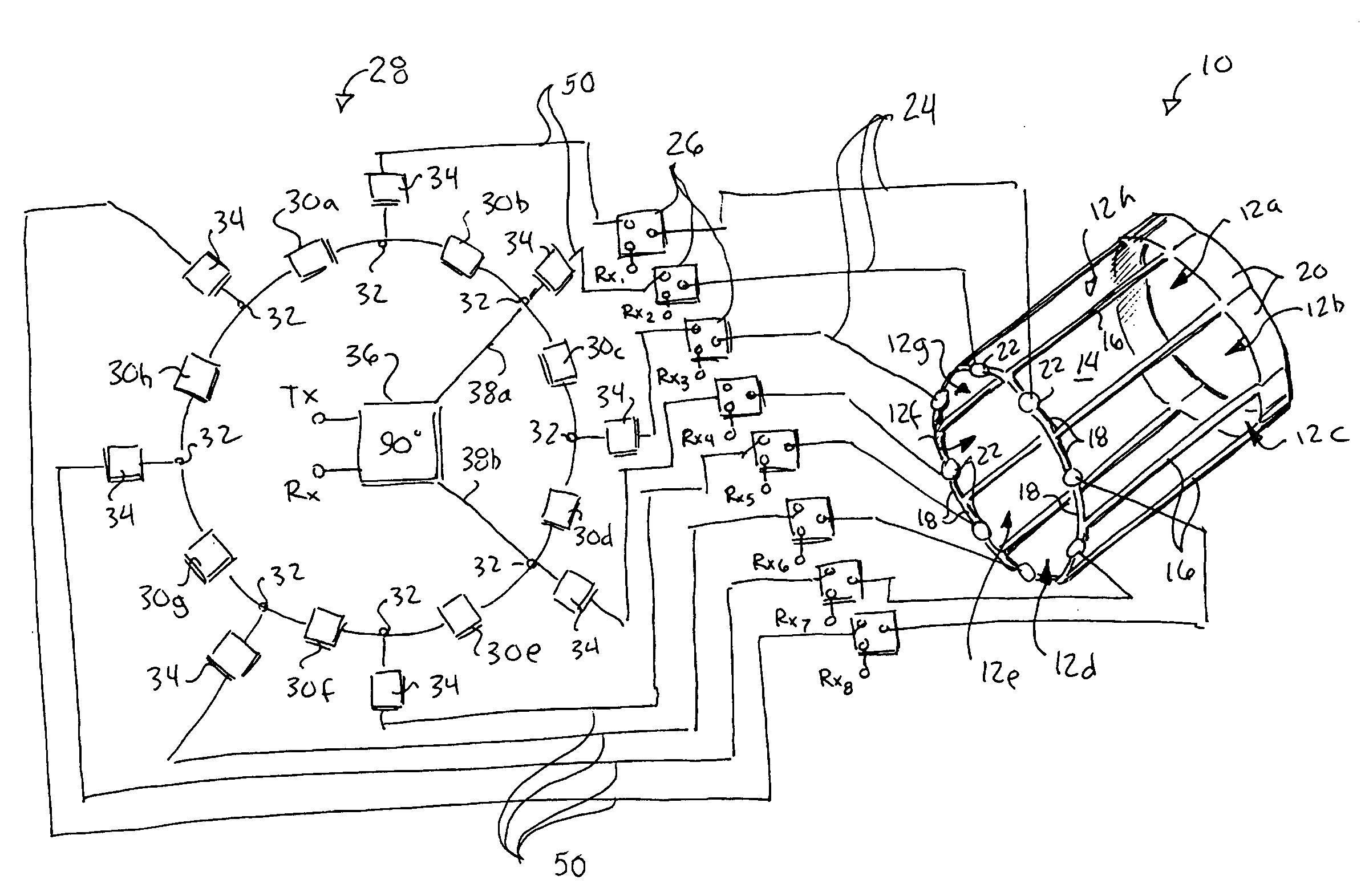
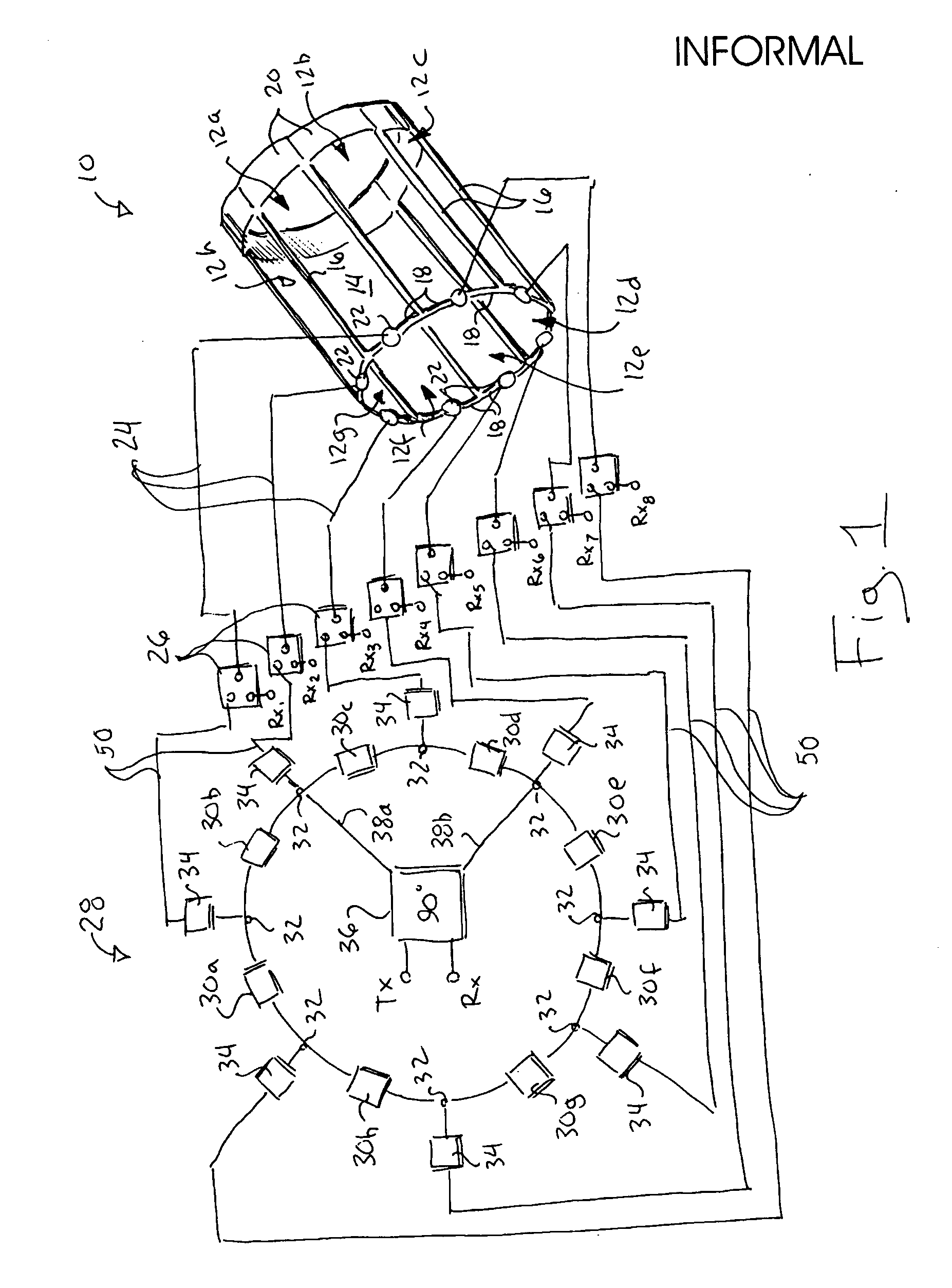
[0038] Referring now to FIG. 1, a head coil 10 suitable for use with the present invention may provide for a series of rectangular conductive loops 12a-12h arrayed about a cylindrical volume 14 to follow the curved circumference of the cylindrical volume.

[0039] Each loop 12 includes axial struts 16 which may be shared by adjacent loops 12 and circumferential struts 18 at one end and circumferential struts 20 at a second end of the volume 14.

[0040] The circumferential struts 20 include capacitive de-coupling circuitry reducing the coupling between adjacent loops 12 as described in U.S. patent application Ser. No. 10 / 122,476 filed Apr. 12, 2002, and assigned to the same assignee as the present invention and hereby incorporated by reference.

[0041] Circumferential struts 18 include loop interface circuits 22 which each provide an electrical coupling to a loop 12a-12f so that transmit signals may be input to the loops 12a-12f and receive signals may be collected from the loops 12a-12f...


PUM


Abstract

A coil for magnetic resonance imaging operates in a transmit mode with multiple loops locked together in a phase relationship like a birdcage coil to provide a uniform transmission field, but in a receive mode like a phased array coil, each coil operating independently to produce a separate signal for reception by the MRI machine. Phasing of the coil during transmit mode is provided by a ring resonator controllably coupled to the loops. Controllable coupling is provided by a series of current limiting elements interposed between the resonant ring and the loops of the coil.

Description

CROSS-REFERENCE TO RELATED APPLICATIONS STATEMENT REGARDING FEDERALLY SPONSORED RESEARCH OR DEVELOPMENT BACKGROUND OF THE INVENTION [0001] The present invention relates generally to magnetic resonance imaging (MRI) and in particular to local coils for use in MRI. [0002] In magnetic resonance imaging, a uniform magnetic field is applied to an imaged object, for example, a patient and a radio frequency (RF) excitation signal pulse is applied to excite nuclei within the patient into resonance. This RF excitation pulse will also referred to herein as a “transmit” signal. [0003] After application of the transmit signal, one or more magnetic gradient fields are superimposed on the uniform magnetic field to spatially encode the precessing nuclei, and nuclear magnetic resonance (NMR) signal from the nuclei are received and processed mathematically to produce an image. The NMR signal will also be referred to herein as a “receive” signal. [0004] The transmit and receive signals may be transmi...

Claims


Application Information

Patent Timeline
IPC IPC(8): G01V3/00
CPCG01R33/34046G01R33/3415G01R33/3607
Inventor JEVTIC, JOVANPIKELJA, VELIBOR
Owner INVIVO CORP
Why Eureka
Try Eureka