Honeycomb structure body

a structure body and honeycomb technology, applied in the field of honeycomb structure bodies, can solve the problems of affecting the normal operation of the body, so as to suppress effectively alleviate the effect of thermal stress, and reduce the occurrence of cracks

Active Publication Date: 2006-07-20
IBIDEN CO LTD
View PDF57 Cites 47 Cited by
  • Summary
  • Abstract
  • Description
  • Claims
  • Application Information

AI Technical Summary

Benefits of technology

[0035] According to the first aspect of the present invention, the honeycomb structural body is designed in such a manner that with respect to the aperture rate X (%) on the inlet side and the total sum Y of thermal capacities of the plugs that seal the group of inlet-side through holes at 500° C. per 11.8 cm2 of the end face on the outlet side containing the group of the outlet-side through holes, the relationship indicated by the above-mentioned in equalities (1) and (2) is satisfied; therefore, it becomes possible to prevent the outlet-side sealing portions from locally having a high temperature at the time of the regenerating process, and also to alleviate a thermal stress imposed on the outlet-side sealing portions to suppress occurrence of cracks therein. Moreover, with respect to the relationship among the aperture rate X on the inlet side, the total sum Y of thermal capacities of the plugs that seal the group of inlet-side through holes at 500° C. per 11.8 cm2 of the end face on the outlet side containing the group of the outlet-side through holes, and / or the total sum Z of thermal capacities of the plugs that seal the group of inlet-side through holes at 25° C., the above-mentioned inequalities (3) to (5) are satisfied so that it becomes possible to more effectively alleviate a thermal stress imposed on the outlet-side sealing portions, and consequently to suppress occurrence of cracks.
[0036] In the honeycomb structural body according to the first aspect of the present invention, in case porous silicon carbide is used as the porous ceramic material, it becomes possible to provide a superior thermal conductivity, heat resistance, mechanical properties, chemical resistance and the like.
[0037] In the honeycomb structural body according to the second aspect of the present invention, a plurality of honeycomb structural bodies according to the first aspect of the present invention are combined with one another through sealing material layer; therefore, it becomes possible to reduce a thermal stress by using the sealing material layer to improve heat resistance, and it also becomes possible to freely adjust the size by increasing or reducing the number of the honeycomb structural bodies according to the first aspect of the present invention. The honeycomb structural body according to the second aspect of the present invention is of course allowed to exert the same effects as the honeycomb structural body according to the first aspect of the present invention.

Problems solved by technology

In recent years, particulates, such as soot, contained in exhaust gases that are discharged from internal combustion engines of vehicles, such as buses and trucks, and construction machines, have raised serious problems as those particulates are harmful to the environment and the human body.
However, the filters having a greater aperture rate on the inlet side have a problem that cracks tend to occur in the plugs that seal the group of inlet-side through holes and the vicinity thereof (hereinafter, may be referred to as outlet-side sealing portions) at the time of the regenerating process.

Method used


Image

  • Honeycomb structure body
  • Honeycomb structure body
  • Honeycomb structure body

Examples


example 1

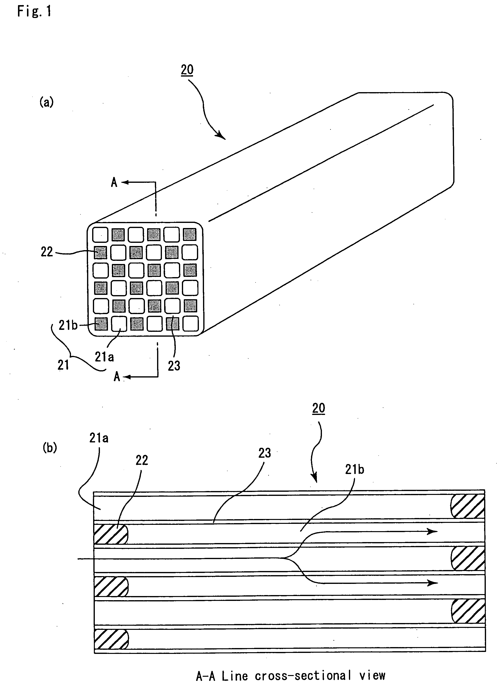
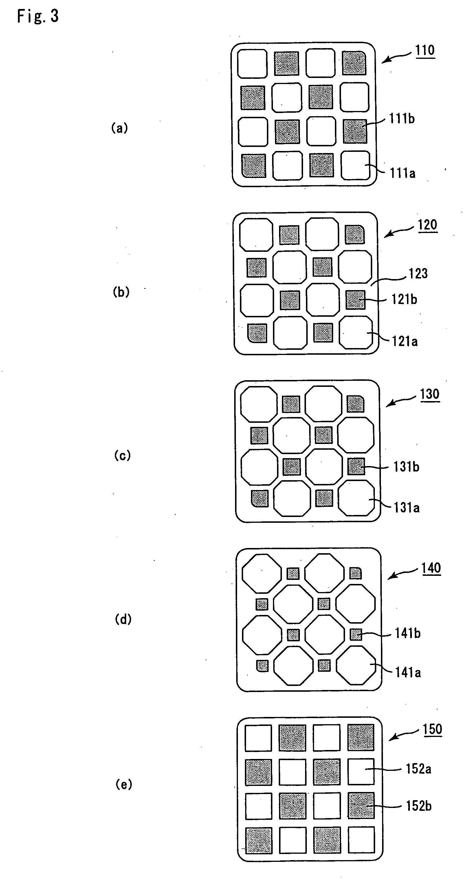
[0144] Powder of α-type silicon carbide having an average particle size of 10 μm (60% by weight) and powder of β-type silicon carbide having an average particle size of 0.5 μm (40% by weight) were wet-mixed, and to 100 parts by weight of the resulting mixture were added and kneaded 5 parts by weight of an organic binder (methyl cellulose) and 10 parts by weight of water to prepare a mixed composition. Next, after a slight amount of a plasticizer and a lubricant had been added and kneaded therein, the resulting mixture was extrusion-molded so that a raw molded product having a cross-sectional shape that was approximately the same cross-sectional shape shown in FIG. 3(a), with an aperture rate on the inlet side of 37.97% and a ratio of aperture rates of 1.52, was manufactured.

[0145] Next, after the above-mentioned raw molded product had been dried by using a micro-wave drier or the like to form a ceramic dried body, predetermined through holes were filled with a sealing material past...

examples 2 to 24

, Comparative Examples 1 to 8

[0152] The same processes as those of Example 1 were carried out except that the cross-sectional shape (inlet-side aperture rate, ratio of aperture rates) perpendicular to the length direction of the integral honeycomb structural body 20 and the thickness of the plugs 22 were changed as indicated by Table 1 to manufacture an integral honeycomb structural body 10.

[0153] Here, the cross-sectional shape in the length direction of the integral honeycomb structural body 20 was adjusted by changing the shape of a die used for extrusion-molding the mixture composition. Moreover, the thickness of the plugs 22 was adjusted by changing the filling amount of the sealing material paste (plug) to the through holes 21.

(Evaluation)

[0154] As shown in FIG. 8, each of the aggregated honeycomb structural bodies of the examples and comparative examples was placed in an exhaust passage of an engine to form an exhaust gas purifying device, and the engine was driven at the...


PUM

PropertyMeasurementUnit
thicknessaaaaaaaaaa
temperatureaaaaaaaaaa

Abstract

An object of the present invention is to provide a honeycomb structural body which makes it possible to prevent a thermal stress from concentrating on plugs for sealing a group of inlet-side through holes and the vicinity thereof during a regenerating process, and consequently to prevent occurrence of cracks. The honeycomb structural body of the present invention is a pillar-shaped honeycomb structural body mainly made of porous ceramics, in which a plurality of through holes are placed in parallel with one another in the length direction with a partition wall interposed therebetween. Herein, the through holes are constituted by a group of inlet-side through holes, whose ends are sealed by plugs at the outlet side such that the total sum of areas on cross sections perpendicular to the length direction is made relatively greater, and a group of outlet-side through holes, whose ends are sealed by plugs at the inlet side such that the total sum of areas on the cross sections thereof is made relatively smaller. Supposing that the aperture rate on the inlet side is X (%) and that the total sum of thermal capacities of the plugs which seal the group of inlet-side through holes at 500° C. per 11.8 cm2 of the end face on the outlet side containing the group of the outlet-side through holes is represented by Y(J / K), the relationship indicated by the following inequalities (1) and (2) is satisfied. 0.0157X−0.0678<Y<1.15X−5  (1) 35≦X≦60  (2)

Description

TECHNICAL FIELD [0001] This application claims benefit of priority to Japanese Patent Application No. 2003-363783, filed on Oct. 23, 2003, the contents of which are incorporated by reference herein. [0002] The present invention relates to a honeycomb structural body used as a filter for removing particulates and the like contained in exhaust gases discharged from an internal combustion system such as a diesel engine, a catalyst supporting member and the like. BACKGROUND ART [0003] In recent years, particulates, such as soot, contained in exhaust gases that are discharged from internal combustion engines of vehicles, such as buses and trucks, and construction machines, have raised serious problems as those particulates are harmful to the environment and the human body. [0004] Various honeycomb structural bodies made of porous ceramics, which serve as filters capable of collecting particulates in exhaust gases to purify the exhaust gases, have been proposed. [0005] Conventionally, wit...

Claims


Application Information

Patent Timeline
Patent Type & Authority Applications(United States)
IPC IPC(8): B01J8/02B01D50/00F01N3/02B01D39/20B01D46/00B01D46/24B01D53/86B01J27/224B01J32/00B01J35/04C04B38/00F01N3/28
CPCB01D46/0063B01D46/244B01D46/2444B01D46/2451B01D46/2459B01D46/247B01D2046/2496B01J35/04C04B38/0006C04B2111/00793C04B2111/0081C04B35/00C04B38/0012B01D46/2498B01D46/84B01D46/2484B01D46/24494B01D46/2476B01D46/2478B01D39/20B01D46/00B01D53/86B01J27/224B01D46/2486
Inventor OHNO, KAZUSHIGEOSHIMI, YUKIO
Owner IBIDEN CO LTD
Why Eureka
Try Eureka