Universal interface for a micro-fluidic chip

a microfluidic chip and interface technology, applied in the direction of immobilised enzymes, fluid pressure measurement by electric/magnetic elements, positive displacement liquid engines, etc., can solve the problems of inability to achieve the same speed, cheapness, precision, and safety with macro-scale process configurations, and little attention to fluid and power management. , to achieve the effect of improving the performance of the ce chip

Inactive Publication Date: 2006-07-27
OCTROLIX
View PDF2 Cites 42 Cited by
  • Summary
  • Abstract
  • Description
  • Claims
  • Application Information

AI Technical Summary

Benefits of technology

[0029] In some embodiments, the integrated CE system incorporates EMI shielding. The shielding improves the performance of

Problems solved by technology

In short, there are things that can be done at the micro-scale that simply cannot be done, or cannot be done as quickly, cheaply, precisely, or as safely with macro-scale process configurations.
While the CE chip provides an efficient platform for conducting capillary electrophoresis, there are drawbacks associated with its use.
In particular, little attention has been paid to fluid and power management; these resources are not efficiently integrated with the CE chip.
Since sample and carrier fluids are manually added to the CE chip via

Method used


Image

  • Universal interface for a micro-fluidic chip
  • Universal interface for a micro-fluidic chip
  • Universal interface for a micro-fluidic chip

Examples


Embodiment Construction

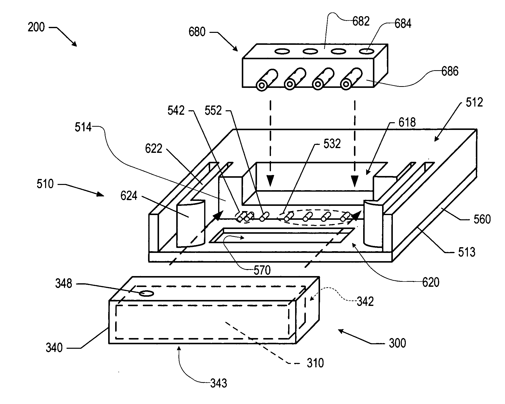
[0043] The illustrative embodiment of the present invention is an integrated capillary electrophoresis system comprising a universal interface and a CE chip. The CE chip is a lab-on-a-chip type device on which the capillary electrophoresis process is conducted. The universal interface enables the operation of the system by facilitating the transfer of one or more of: fluids, electrical energy, and electrical and optical signals between the external environment and the CE chip.

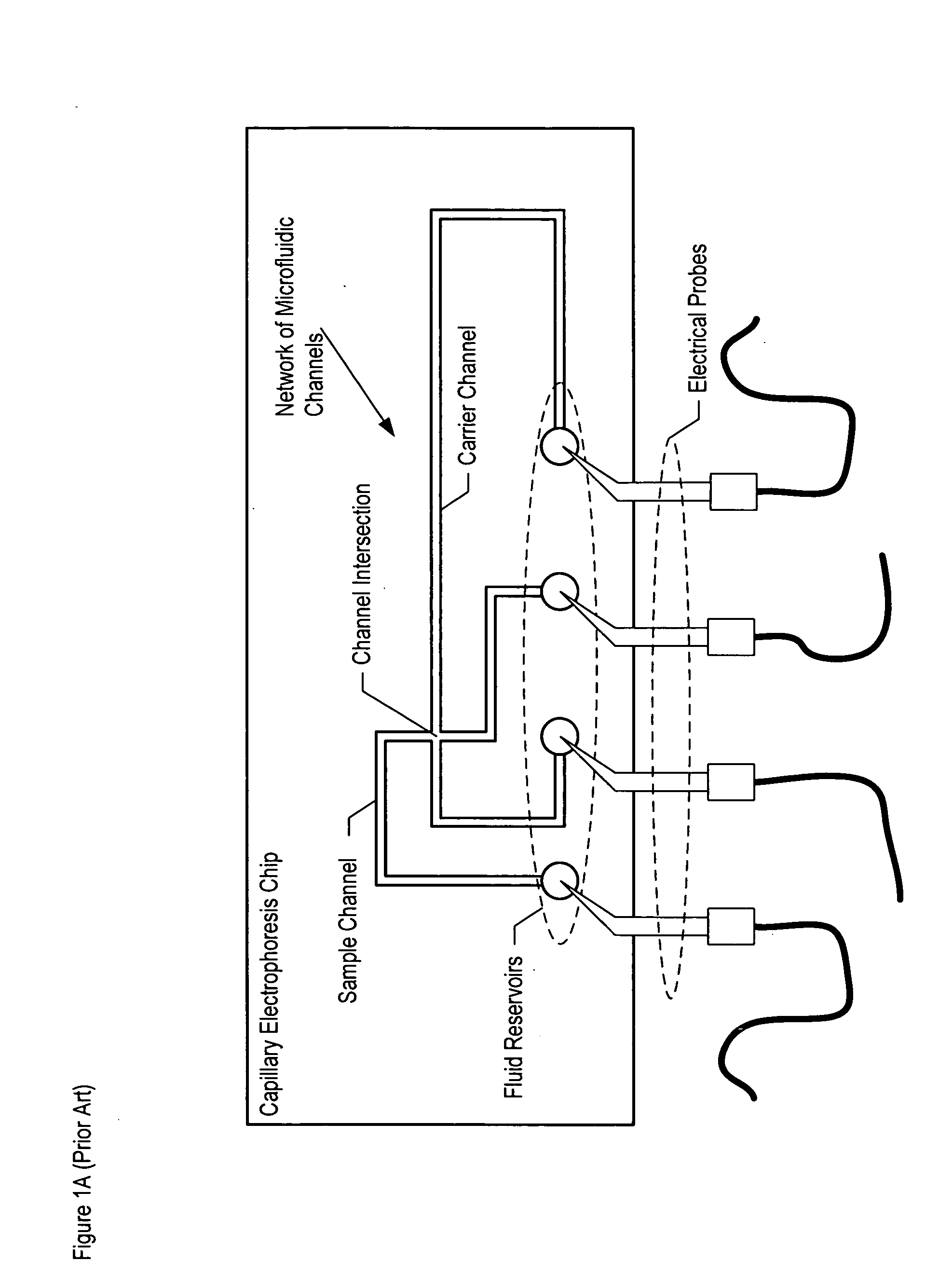
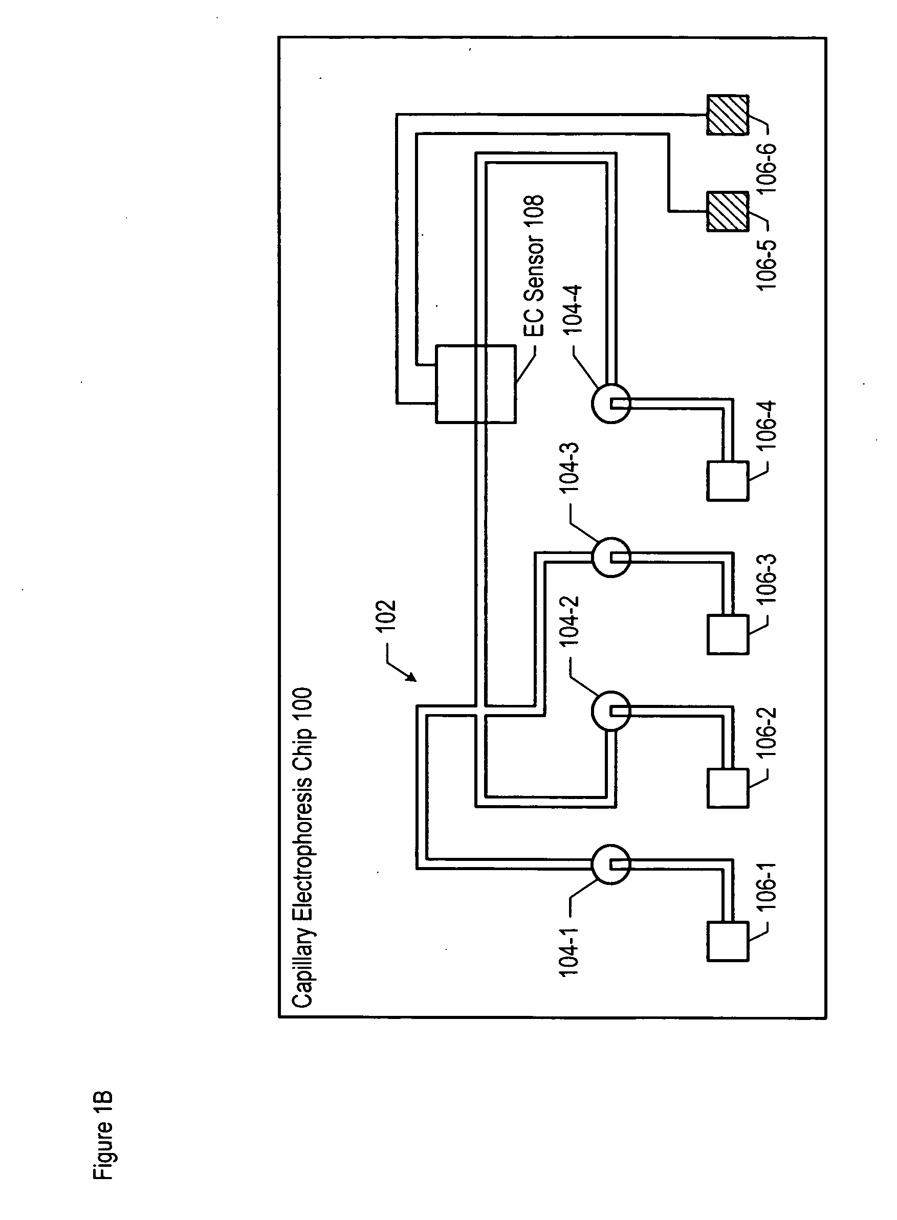
[0044] This disclosure begins with a description of the CE chip 100. In accordance with the illustrative embodiment, the CE chip is coupled to the universal interface to provide an integrated CE system. The elements of the universal interface are depicted in FIGS. 3, 4A-4D, 5, 6, and 7A-7D. But before these elements are described, context is provided by way of the block diagram of FIG. 2, which depicts the integrated CE system coupled to a variety of auxiliary systems for conducting a capillary electrophoresis...


PUM

PropertyMeasurementUnit
Electrical conductoraaaaaaaaaa
Energyaaaaaaaaaa

Abstract

An integrated capillary electrophoresis system comprising a universal interface is disclosed. The universal interface includes one or more of the following structural elements: a chip assembly that receives a capillary electrophoresis CE chip; a fluidic interface for coupling fluids between the chip assembly and external sources or destinations; a first electrical interface for coupling power from an external source to the chip assembly; a second electrical interface for coupling electrical signals from the chip assembly to external analysis electronics; an optical interface for coupling optical signals between the chip assembly and external sources or destinations; and a docking station for uniting and spatially locating the various other structural elements.

Description

FIELD OF THE INVENTION [0001] The present invention relates to micro-fluidic chips in general, and, more particularly, to fluidic, electrical and optical interfaces for use with micro-fluidic chips. BACKGROUND OF THE INVENTION [0002] The term “micro-fluidics” refers to technologies that involve the manipulation of very small amounts (typically nano-liter to micro-liter quantities) of liquids or gases. Micro-fluidic technologies are now used to carryout a variety of chemical and biological processes. Many benefits are realized by conducting these types of processes at the micro-scale. In short, there are things that can be done at the micro-scale that simply cannot be done, or cannot be done as quickly, cheaply, precisely, or as safely with macro-scale process configurations. [0003] Micro-fluidic processes are usually conducted in a network of micro-channels. These micro-channels, which are typically only tens of microns deep and wide, are usually formed via lithographic processing a...

Claims


Application Information

Patent Timeline
IPC IPC(8): G01N27/447C07K1/26B01L99/00
CPCB01L3/5027B01L9/527B01L2200/025B01L2200/027B01L2200/04B01L2300/0654B01L2400/0421G01N21/05G01N27/44704G01N2021/0346
Inventor PRAK, ALBERTVAN DEN VLEKKERT, HENDRIK HARMEN
Owner OCTROLIX
Why Eureka
Try Eureka