Ion beam therapy system and its couch positioning method

a couch positioning and therapy system technology, applied in the direction of patient positioning for diagnostics, therapy, instruments, etc., can solve the problems of prolonged difficult to obtain clear and accurate information, and increase the treatment time per patient, so as to reduce the time required for positioning the couch and increase the accuracy of positioning

Active Publication Date: 2006-07-27
BOARD OF RGT THE UNIV OF TEXAS SYST +1
View PDF10 Cites 129 Cited by
  • Summary
  • Abstract
  • Description
  • Claims
  • Application Information

AI Technical Summary

Benefits of technology

[0010] On the other hand, with the positioning process described in from line 67, column 9 to line 18, column 11 of U.S. Pat. No. 5,039,867, a three-dimensional current tomographic image including the tumor can be formed by employing the X-ray CT technique. In comparison with the positioning process using the X-ray image described in U.S. Pat. No. 5,825,845, therefore, the couch can be positioned at higher accuracy by using the current tomographic image and the reference tomographic image.
[0011] It is sometimes necessary to combine the rotation of the beam delivery unit with positioning the couch in the horizontal direction, disclosed in FIGS. 1, 2 and 11 of U.S. Pat. No. 6,094,760(JP, A 11-313900) so that the direction of irradiation of the ion beam with respect to the tumor can be more freely set. In the case of employing the beam delivery unit mounted to the rotating gantry to accomplish such a goal, however, because the couch is positioned by using a temporarily moved X-ray CT unit and a current tomographic image obtained by the X-ray CT unit as disclosed in U.S. Pat. No. 5,039,867, the time required for positioning the couch is prolonged and the treatment time per patient is increased. More specifically, a couch used in a particle beam therapy system, on which the patient is lying, is moved in the X-, Y- and Z-directions and further rotated in the horizontal direction by a moving apparatus disclosed in U.S. Pat. No. 6,094,760. Then, while keeping the position of the couch as it is, an X-ray CT unit is moved to a position on an extension of the beam path of the beam delivery unit where a current tomographic image including the tumor is then obtained. At this time, the couch is located in the X-ray CT unit. After the end of image acquisition by the X-ray CT unit, the X-ray CT unit is moved away from the beam delivery unit to a position out of interference with the irradiation of an ion beam. Those movements for setting and retracting the X-ray CT unit increase the time required for positioning the couch. It is difficult and takes a longer time, in particular, to move the X-ray CT unit without moving the couch such that the couch is located in the X-ray CT unit and the X-ray CT unit is moved to the position on the extension of the beam path. Furthermore, since the isocenter of the X-ray CT does not necessarily coincide with that of the rotating gantry, it is necessary that the image obtained by the X-ray CT is transformed to that in the coordinate around the isocenter of the rotating gantry. This also extends the time for the preparation of the treatment for a patient.
[0012] Accordingly, it is an objective of the present invention to provide a therapy system using an ion beam, and a couch positioning method, which can reduce the time required for positioning a patient couch in order to achieve an accurate positioning of the target volume within the therapeutic radiation field.
[0014] With the present invention, both the X-ray generator and X-ray detection unit mounted to the rotating gantry are operated at various rotating angles of the rotating gantry, and three dimensional tomographic information of the irradiation target is formed by using information obtained based on the X-ray detection signals outputted respectively from the X-ray detection unit, there is no need of moving an X-ray CT unit for positioning the couch to the position of the radiation path and retreating the X-ray CT unit to a position out of interference with irradiation of the first radiation to the irradiation target after capturing an X-ray CT image. There is also no need for the transformation of the radiographic image or the irradiation target's coordinate which was necessary in the case using the above separate X-ray CT unit. As a result, the time required for positioning the couch can be cut down and the accuracy of positioning the tumor increased.
[0015] Preferably, the X-ray generator is provided in the beam delivery unit and is movable between a first position lying in the radiation path and a second position away from the radiation path. With this feature, the X-ray generator can be easily moved between the first position and the second position, and a structure for mounting the X-ray generator to the rotating gantry can be simplified.
[0017] Hence, according to the present invention, it is possible to reduce the time required for positioning the couch (patient) in order to align the tumor with the therapeutic radiation field while simultaneously increase the accuracy of the positioning.

Problems solved by technology

It has been, therefore, not easy to obtain clear and accurate information regarding the shape and position of the tumor in the patient's body (hereinafter referred to simply as “position information”) which is three-dimensional in nature.
In the case of employing the beam delivery unit mounted to the rotating gantry to accomplish such a goal, however, because the couch is positioned by using a temporarily moved X-ray CT unit and a current tomographic image obtained by the X-ray CT unit as disclosed in U.S. Pat. No. 5,039,867, the time required for positioning the couch is prolonged and the treatment time per patient is increased.
Those movements for setting and retracting the X-ray CT unit increase the time required for positioning the couch.
It is difficult and takes a longer time, in particular, to move the X-ray CT unit without moving the couch such that the couch is located in the X-ray CT unit and the X-ray CT unit is moved to the position on the extension of the beam path.

Method used


Image

  • Ion beam therapy system and its couch positioning method
  • Ion beam therapy system and its couch positioning method
  • Ion beam therapy system and its couch positioning method

Examples


Embodiment Construction

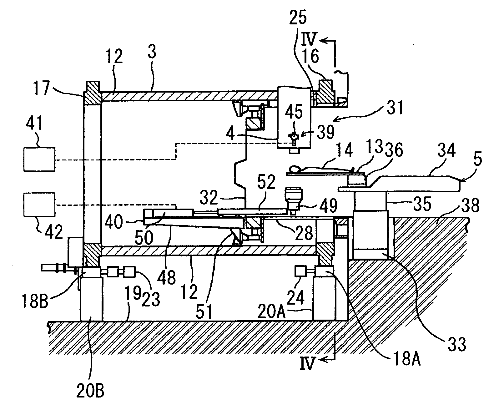
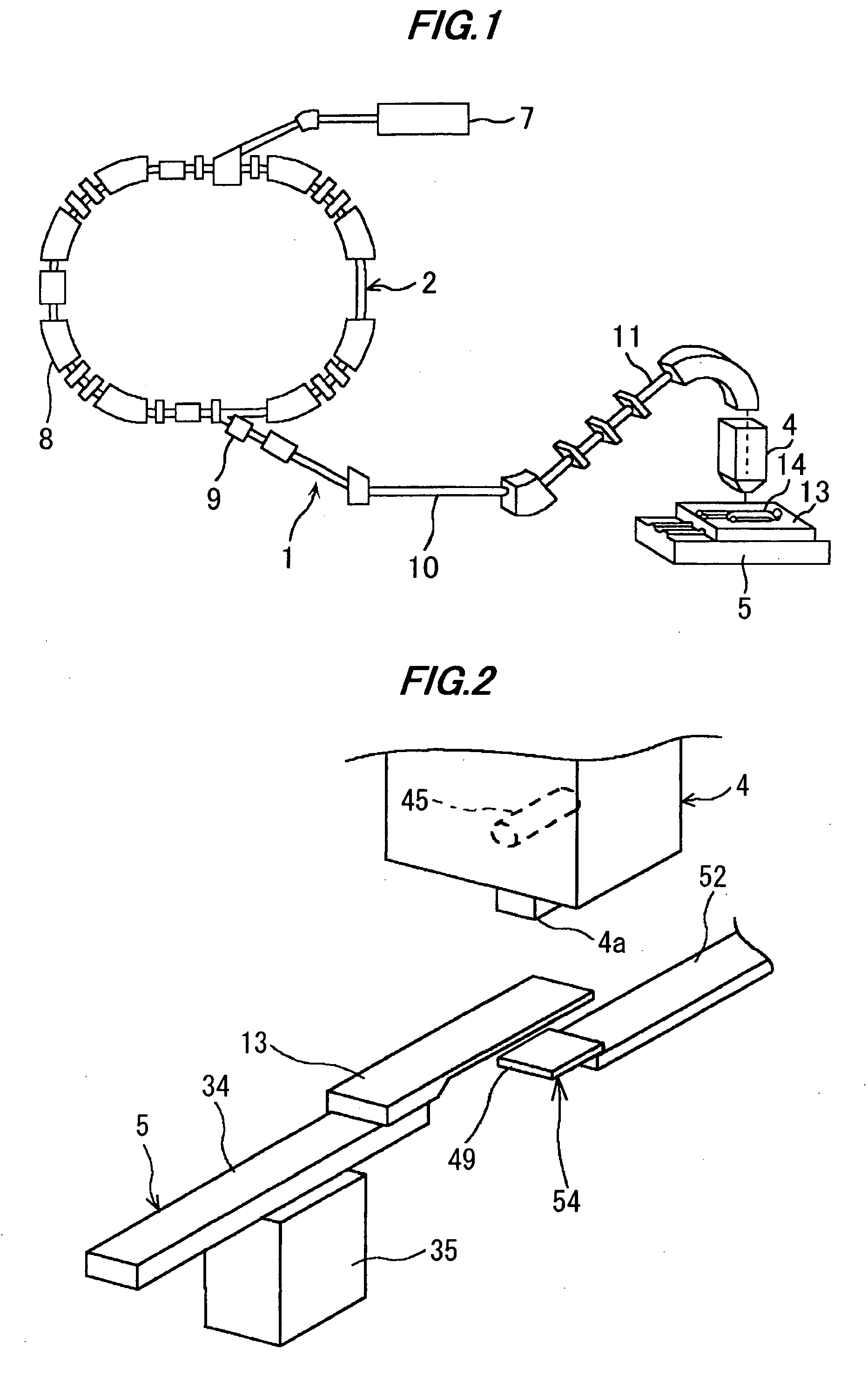
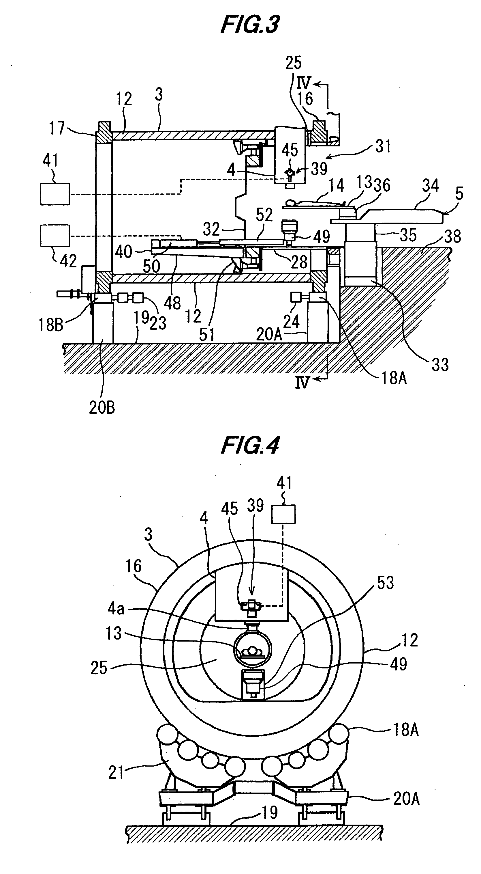
[0030] A radiation therapy system according to one preferable embodiment of the present invention will be described below with reference to FIGS. 1 to 11. A therapy system 1 constituting the radiation therapy system of this embodiment comprises a beam generator 2, a rotating gantry 3 (see FIG. 3), a beam delivery unit 4, a treatment bench 5 (see FIG. 2), and a couch positioning apparatus 6 (see FIG. 5). The couch positioning apparatus 6 comprises an X-ray source device (X-ray generator) 39, an image receiving system 40, an X-ray source controller 41, and an image receptor movement controller 42. The radiation therapy system of this embodiment is a cancer treatment system. The beam generator 2 comprises an ion source (not shown), a pre-stage accelerator 7, and a synchrotron 8. Ions (e.g., proton ions or carbon ions) generated from the ion source are accelerated by the pre-stage accelerator (e.g., a linear accelerator) 7. A resulting ion beam (e.g., a proton beam) enters the synchrotr...


PUM

PropertyMeasurementUnit
widthaaaaaaaaaa
setting angleaaaaaaaaaa

Abstract

A therapy system using an ion beam, which can shorten the time required for positioning a couch (patient). The therapy system using the ion beam comprises a rotating gantry provided with an ion beam delivery unit including an X-ray tube. An X-ray detecting device having a plurality of X-ray detectors can be moved in the direction of a rotation axis of the rotating gantry. A couch on which a patient is lying is moved until a tumor substantially reaches an extension of an ion beam path in the irradiating unit. The X-ray tube is positioned on the ion beam path and the X-ray detecting device is positioned on the extension of the ion beam path. With rotation of the rotating gantry, both the X-ray tube emitting an X-ray and the X-ray detecting device revolve around the patient. The X-ray is emitted to the patient and detected by the X-ray detectors after penetrating the patient. Tomographic information of the patient is formed based on signals outputted from the X-ray detectors. Information for positioning the couch is generated by using the tomographic information.

Description

BACKGROUND OF THE INVENTION [0001] 1. Field of the Invention [0002] The present invention relates to a therapy system using a radiation and a method of positioning a patient couch. More particularly, the present invention relates a therapy system using an ion beam, such as a proton or a carbon ion beam, to a tumor (diseased tissue) for treatment, and a couch positioning method. [0003] 2. Description of the Related Art [0004] There is known a therapy method of setting an irradiation target center at a tumor, e.g., a cancer, in a patient's body and delivering an ion beam, such as a proton or carbon ion beam, to the tumor. An ion beam therapy system with such a therapy method comprises a beam generator consisting of an accelerator and a beam transport system, and a beam delivery unit mounted to a rotating gantry. Ion beam accelerated by the accelerator reaches the beam delivery unit through the beam transport system, and is monitored and shaped to conform to the shape of the tumor in t...

Claims


Application Information

Patent Timeline
Patent Type & Authority Applications(United States)
IPC IPC(8): A61N5/01A61N5/10
CPCA61N5/1049A61N5/1069A61N2005/1061A61N2005/1087
Inventor HIRAMOTO, KAZUOAKIYAMA, HIROSHINAGAMINE, YOSHIHIKOSMITH, ALFREDNEWHAUSER, WAYNE
Owner BOARD OF RGT THE UNIV OF TEXAS SYST
Why Eureka
Try Eureka