Supercharge Your Innovation With Domain-Expert AI Agents!

Solid state electric generator

a solid-state electric generator and generator technology, applied in the direction of magnetic circuit rotating parts, magnetic circuit shapes/forms/construction, magnetic bodies, etc., can solve the problem that the total magnetic field produced by these atoms cannot be easily moved, and achieve the effect of effective movement and vibrating

Inactive Publication Date: 2006-07-27
CHAVA ENERGY
View PDF5 Cites 13 Cited by
  • Summary
  • Abstract
  • Description
  • Claims
  • Application Information

AI Technical Summary

Benefits of technology

[0011] In specific ferromagnetic materials, the orientation axis of each atomic electromagnet is flexible. The orientation of magnetic flux within, as well as external to the material, easily pivots. Such materials are referred to as magnetically “soft”, due to this magnetic flexibility.
[0013] The axis of circular current flow in one ferromagnetic atom can direct the axis of magnetism within another ferromagnetic atom, through a process known as spin exchange. This gives a soft magnetic material, like raw iron, the useful ability to aim, focus, and redirect the magnetic field emitted from a magnetically hard permanent magnet.
[0014] In the present invention, a permanent magnet's rigid field is sent into a magnetically flexible, “soft” magnetic material. The permanent magnet's apparent location, observed from points within the magnetically soft material, will effectively move, vibrate, and appear to shift position when the magnetization of the soft magnetic material is modulated by ancillary means (much like the sun, viewed while underwater, appears to move when the water is agitated). By this mechanism, the motion required for generation of electricity can be synthesized within a soft ferromagnetic material, without requiring physical movement or an applied mechanical force.

Problems solved by technology

The total magnetic field produced by these atoms cannot easily move.

Method used


Image

  • Solid state electric generator
  • Solid state electric generator
  • Solid state electric generator

Examples


Embodiment Construction

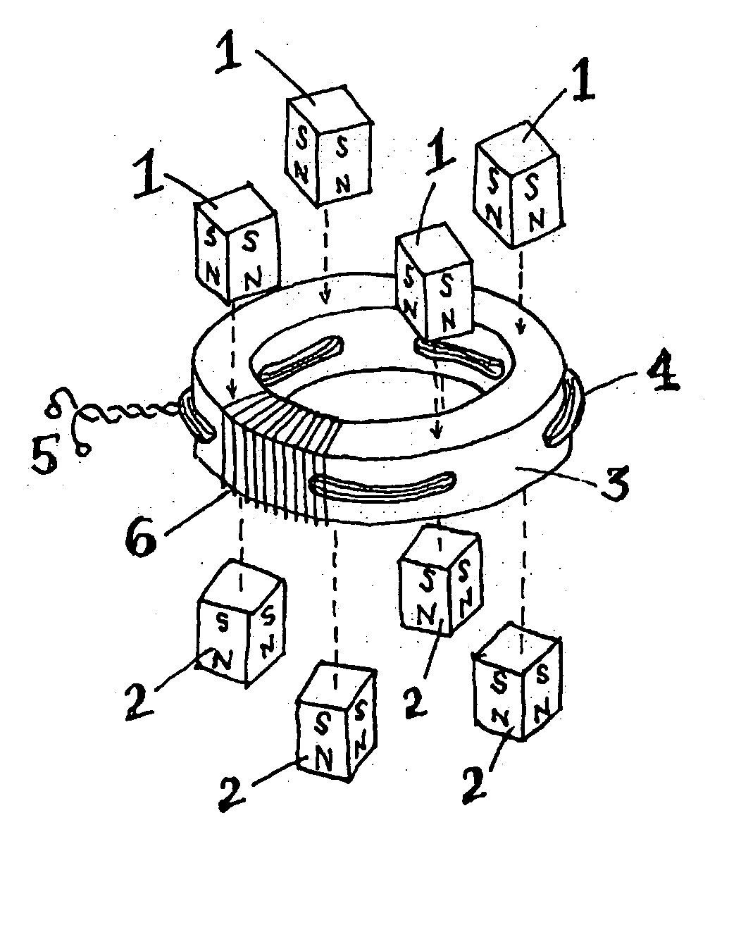
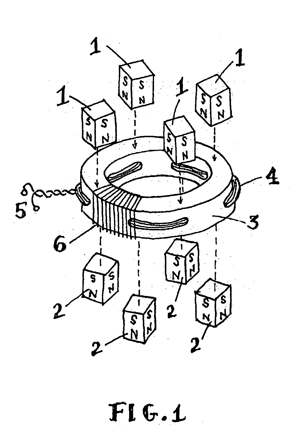
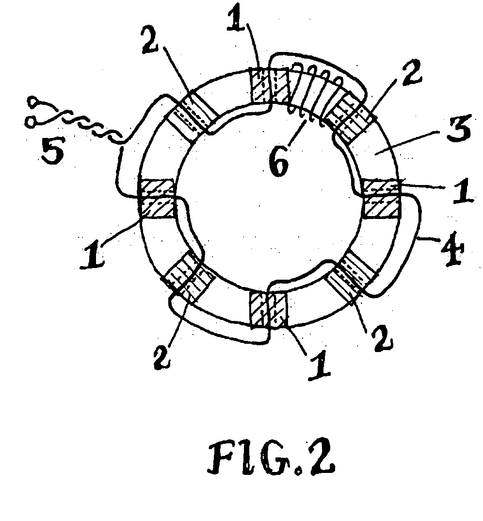
[0021]FIG. 1 depicts a partially exploded view of an embodiment of an electric generator of this invention. The parts have been numbered, with the numbering convention applied to FIGS. 1, 2, and 3.

[0022] Numeral 1 represents a permanent magnet with its North pole pointing inward toward the soft ferromagnetic core of the device. Similarly, numeral 2 indicates permanent magnets of preferably the same shape and composition, with their South poles aimed inward toward the opposite side, or opposite surface of the device. The letters “S” and “N” denote these respective magnetic poles in the drawing. Other magnetic polarities and configurations may be used with success; the pattern shown merely illustrative of one efficient mode of adding magnets to the core.

[0023] The magnets may be formed of any polarized magnetic material. In order of descending effectiveness, the most desirable permanent-magnet materials are Neodymium-Iron-Boron (NIB) magnets, Samarium Cobalt magnets, AlNiCo alloy ma...


PUM

PropertyMeasurementUnit
volumeaaaaaaaaaa
magnetic fluxaaaaaaaaaa
electromotive forceaaaaaaaaaa

Abstract

A solid-state electrical generator including at least one permanent magnet, magnetically coupled to a ferromagnetic core provided with at least one hole penetrating its volume; the hole(s) and magnet(s) being placed such that the hole(s) penetrating the ferromagnetic core's volume intercept flux from the permanent magnet(s) coupled into the ferromagnetic core. A first wire coil is wound around the ferromagnetic core for the purpose of moving the coupled permanent magnet flux within the ferromagnetic core. A second wire is routed through the hole(s) penetrating the volume of the ferromagnetic core, for the purpose of intercepting this moving magnetic flux, thereby inducing an output electromotive force. A changing voltage applied to the first wire coil causes coupled permanent magnet flux to move within the core relative to the hole(s) penetrating the core volume, thus inducing electromotive force along wire(s) passing through the hole(s) in the ferromagnetic core. The mechanical action of an electrical generator is thereby synthesized without use of moving parts.

Description

[0001] This application claims priority to Provisional Application 60 / 645,674 filed Jan. 21, 2005, entitled PERMANENT MAGNET DRIVEN ELECTRIC GENERATOR.BACKGROUND OF THE INVENTION [0002] 1. Field of the Invention [0003] This invention relates to a method and device for generating electrical power using solid state means. [0004] 2. Description of the Related Art [0005] It has long been known that moving a magnetic field across a wire will generate an electromotive force (EMF), or voltage, along the wire. When this wire is connected in an electrical closed circuit, in order to perform work, an electric current is driven through this closed circuit by the induced electromotive force. [0006] It has also long been known that this resulting electric current causes the closed circuit to become encircled with a secondary, induced magnetic field, whose polarity opposes the primary magnetic field that first induced the EMF. This magnetic opposition creates mutual repulsion as a moving magnet m...

Claims


Application Information

Patent Timeline
Patent Type & Authority Applications(United States)
IPC IPC(8): H02K1/22H01F3/00
CPCH01F3/00H01F27/306H02K53/00
Inventor GUNDERSON, GRAHAM ALAN
Owner CHAVA ENERGY
Features
  • R&D
  • Intellectual Property
  • Life Sciences
  • Materials
  • Tech Scout
  • Unparalleled Data Quality
  • Higher Quality Content
  • 60% Fewer Hallucinations
Learn More