System having unmodulated flux locked loop for measuring magnetic fields

a technology of magnetic field and flux lock, which is applied in the direction of magnetic measurement, instruments, measurement devices, etc., can solve the problems of small limiting field strength providing little practical value, distortion-producing, non-linear, bulky, and achieves fewer, smaller and less expensive electronic components. , the effect of eliminating distortion-producing, non-linear, bulky and expensive rf components

Active Publication Date: 2006-07-27
HONEYWELL FED MFG & TECHNOLOGI
View PDF32 Cites 7 Cited by
  • Summary
  • Abstract
  • Description
  • Claims
  • Application Information

AI Technical Summary

Benefits of technology

[0020] Thus, it will be appreciated that the system and, more particularly, the FLL of the present invention provides a number of substantial advantages over the prior art, including, for example, that the direct-feedback FLL is the simplest way to linearize the SQUID. The direct-feedback FLL also uses fewer, smaller, and less expensive electronic components; requires fewer adjustments which are easier to make; and eliminates distortion-producing, non-linear, bulky, and expensive RF components used in prior art modulated FLLs.

Problems solved by technology

Without the FLL, the SQUID would have a very limited dynamic range because of its extremely non-linear magnetic field-to-voltage transfer function characteristic.
This small limiting field strength provides little dynamic range and has little practical value.
Systems using SQUIDs for non-destructive testing / evaluation of materials or structures or for making biomagnetic measurements were long impractical for use in field settings (i.e., environments containing high levels of magnetic interference).
In magnetically unshielded environments, large amplitude or high slew rate external stray magnetic fields from 50 / 60 Hz AC power lines, AM broadcast transmitters, small changes in the Earth's magnetic field, and other sources, caused the FLL to lose lock and thereby invalidate any measurement in progress.
Furthermore, the prior art employed traditional twisted-pair wires which were highly undesirable for several reasons, including that they had a high degree of linear attenuation versus frequency that severely distorts square waves of even moderate frequencies, they allowed for a large amount of radiated leakage and corresponding susceptibility to radio-frequency interference, and they had a highly variable characteristic impedance that changed with mechanical stress and was difficult to impedance match.
The incorporation of digital signal processing (DSP) technology into the FLL had been attempted with limited success due to inherent delays associated with signal acquisition, processing and reconstruction of the feedback signal, and the maximum clock frequency of the DSP.
Because of these problems, early attempts to incorporate DSP into the FLL failed to increase the operating frequency above that obtainable with standard analog read-out systems.
For these reasons, SQUIDs were restricted to use in controlled environments shielded from magnetic interference, and were typically expensive, bulky, and non-portable.
Unfortunately, modulation is associated with a greater number of electronic components, a greater number of more difficult adjustments, and distortion-producing non-linear RF components such as, for example, modulation oscillators, that emit RF interference.
Modulation of the SQUID transfer function can also create unwanted distortion and signal sidebands with high level magnetic field signals applied to the SQUID.
Modulated FLLs also require substantial bandwidth to process signal information.
Modulated FLLs are also non-linear and therefore require band-limiting RF filters, which results in lower slew rates and narrower tracking bandwidths

Method used


Image

  • System having unmodulated flux locked loop for measuring magnetic fields
  • System having unmodulated flux locked loop for measuring magnetic fields
  • System having unmodulated flux locked loop for measuring magnetic fields

Examples


Embodiment Construction

, below.

BRIEF DESCRIPTION OF THE DRAWINGS

[0022] A preferred embodiment of the present invention is described in detail below with reference to the attached drawing figures, wherein:

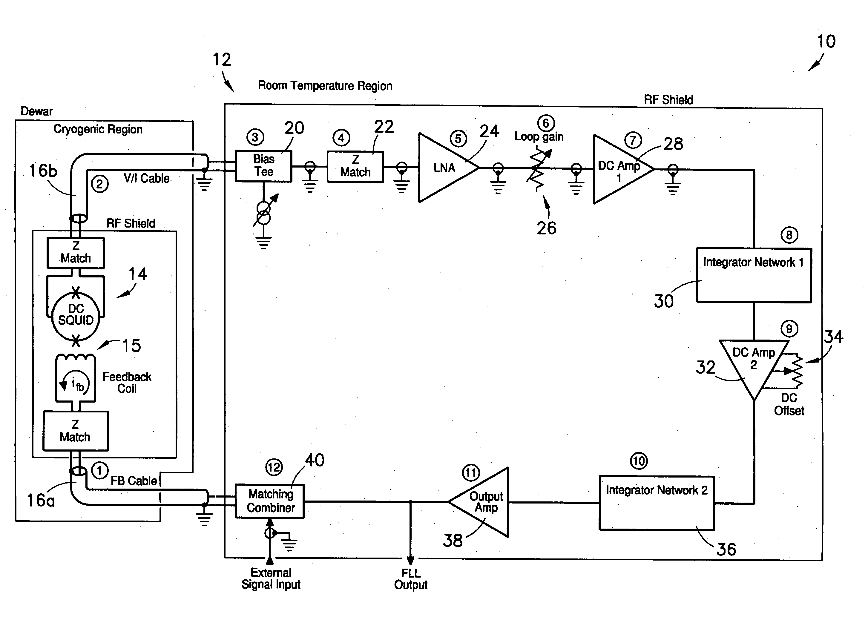
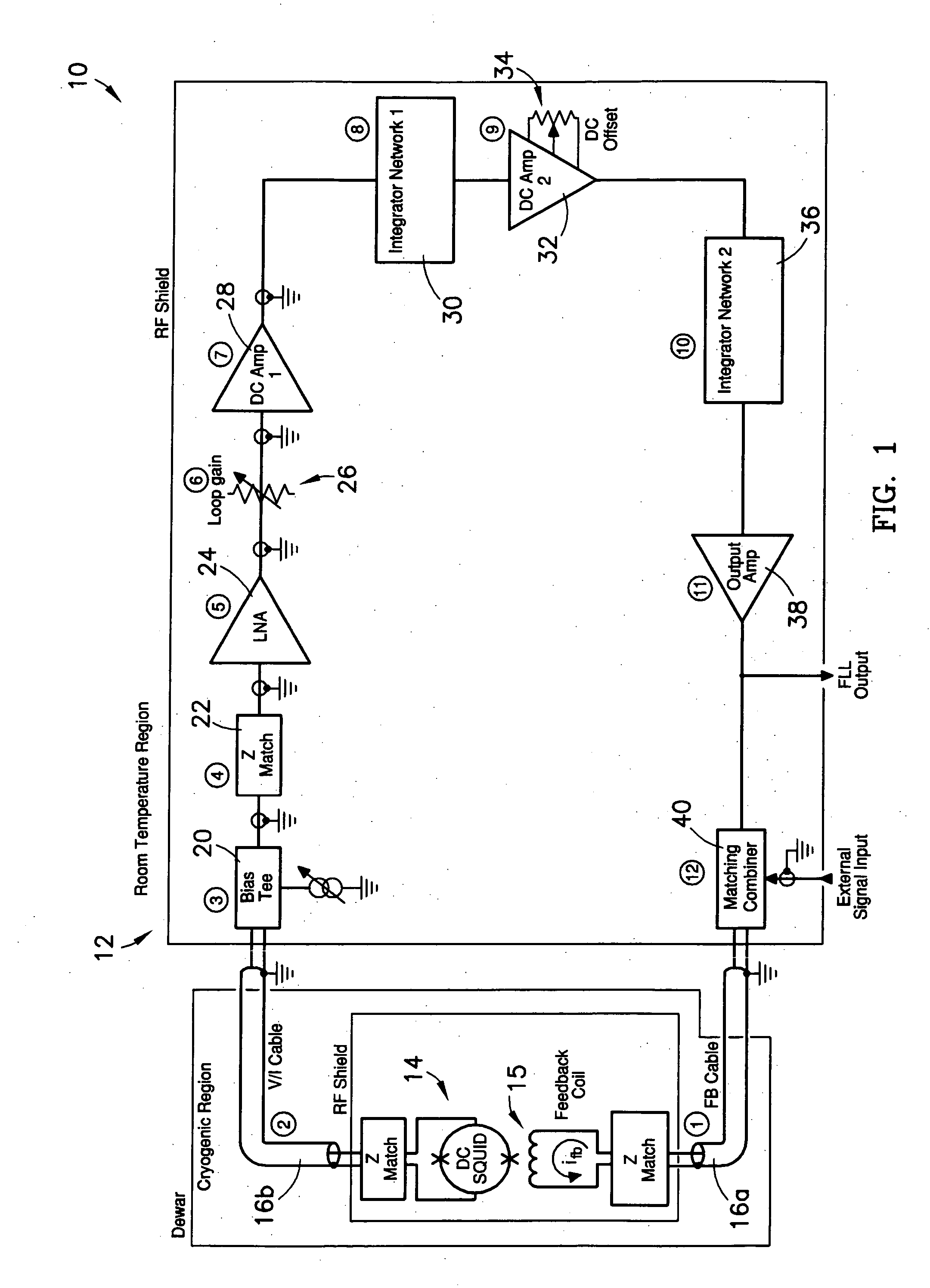
[0023]FIG. 1 is a block diagram showing a preferred embodiment of the system of the present invention, comprising a direct-feedback FLL connected by unbalanced RF coaxial transmission lines to a SQUID;

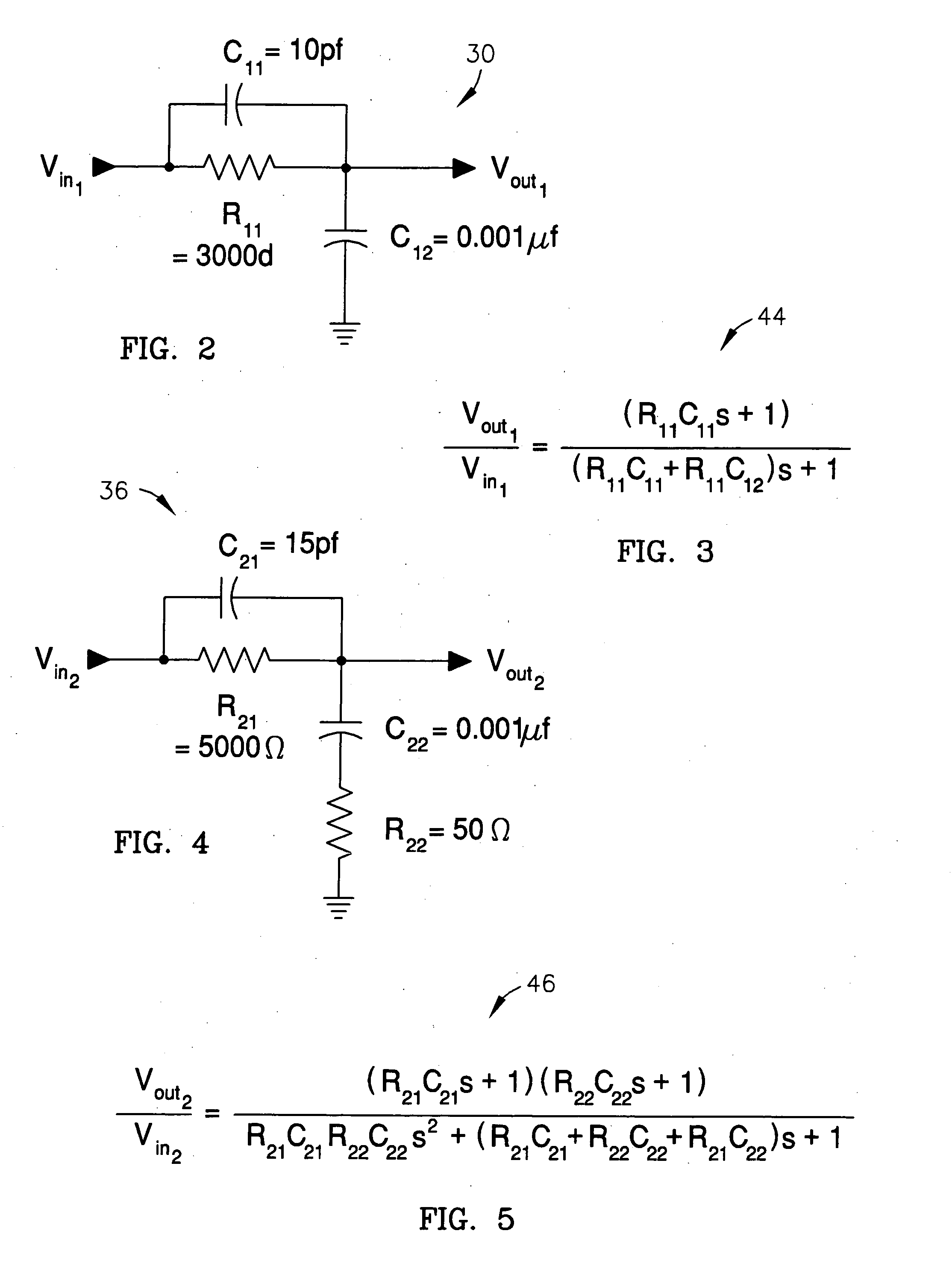
[0024]FIG. 2 is a first circuit schematic of a first integrator network component of the direct-feedback FLL of FIG. 1;

[0025]FIG. 3 is a first equation describing the circuit schematic of FIG. 2;

[0026]FIG. 4 is a second circuit schematic of a second integrator network component of the direct-feedback FLL of FIG. 1; and

[0027]FIG. 5 is a second equation describing the second circuit schematic of FIG. 4.

DETAILED DESCRIPTION OF A PREFERRED EMBODIMENT

[0028] With reference to the figures, a system 10 for measuring magnetic fields is herein described, shown, and otherwise disclosed in accordance with a prefe...


PUM


Abstract

A system (10) for measuring magnetic fields, wherein the system (10) comprises an unmodulated or direct-feedback flux locked loop (12) connected by first and second unbalanced RF coaxial transmission lines (16a,16b) to a superconducting quantum interface device (14). The FLL (12) operates for the most part in a room-temperature or non-cryogenic environment, while the SQUID (14) operates in a cryogenic environment, with the first and second lines (16a,16b) extending between these two operating environments.

Description

FEDERALLY SPONSORED RESEARCH OR DEVELOPMENT PROGRAM [0001] The present invention was developed with support from the U.S. government under Contract No. DE-AC04-01AL66850 with the U.S. Department of Energy. Accordingly, the U.S. government has certain rights in the present invention.BACKGROUND OF THE INVENTION [0002] 1. Field of the Invention [0003] The present invention relates broadly to systems for measuring magnetic fields using flux licked loops and superconducting quantum interface devices. More particularly, the present invention concerns a system comprising an unmodulated or direct-feedback flux locked loop electrically connected by first and second unbalanced coaxial transmission lines to a superconducting quantum interface device. [0004] 2. Description of the Prior Art [0005] Superconducting quantum interface devices (SQUIDs) are small, cryogenically-cooled magnetic field sensors comprising a ring of superconducting material interrupted by two Josephson junctions. SQUIDs ar...

Claims


Application Information

Patent Timeline
Patent Type & Authority Applications(United States)
IPC IPC(8): G01R33/02
CPCG01R33/0354Y10S505/846
Inventor GANTHER, KENNETH R. JR.SNAPP, LOWELL D.
Owner HONEYWELL FED MFG & TECHNOLOGI
Why Eureka
Try Eureka