Apparatus for marking a defect

a technology for defect marking and apparatus, applied in the field of apparatus for defect marking, can solve the problems of reducing the strength of the portion having the physical mark, difficult marking, and clogging of the head, and achieve the effect of efficient placement, easy recognition, and efficient operation

Inactive Publication Date: 2006-07-27
NAGASE & COMPANY
View PDF2 Cites 52 Cited by
  • Summary
  • Abstract
  • Description
  • Claims
  • Application Information

AI Technical Summary

Benefits of technology

[0053] By using the apparatus for marking a defect of the present invention, a mark can be efficiently placed on the portion of defect using an ink of the quick drying type in a short production line having no drying step since the tip of the oil-based marking pen for placing a mark on the portion of defect in a product having a sheet form is not dried. When the portion of defect in the vicinity of the mark can be recognized by visual observation, the ink can be wiped out with a solvent, and the portion of defect alone can be removed or repaired. Therefore, the product having a sheet form can be effectively utilized as the raw material for the final product.
[0054] By using the apparatus for slitting a film as an application of the apparatus for marking a defect of the present invention, slitting the material film, detecting a defect on the film and marking the portion of defect in the product film formed by the slitting can be conducted efficiently in a single step. Since the mark on the portion of defect is clear, the mark can be easily recognized by visual observation or by image processing. The portion of defect can be removed or repaired in a later step of the working in the case of an intermediate product, and the use of the portion of defect can be avoided in the case of the product film as the final product.
[0055] When the apparatus for marking a defect of the present invention is used, since a product having a long sheet form is separated into many rectangles and the presence or the absence of a defect in a rectangle is decided with respect to each rectangle independently of the number of the defect, the mark can be placed accurately with stability at the portion of defect even when many defects are locally concentrated or a great defect extending into many rectangles is present.
[0056] When the apparatus for marking a defect of the present invention is used, since a high voltage is applied to a solenoid for pushing out the marking member only for a short time after the start of application of the voltage, the marking member is quickly pushed out by a strong force

Problems solved by technology

However, the marking to the product having a sheet form depends inevitably on a physical means.
However, when a felt pen is used, the tip of the pen is dried in a short time, and the marking becomes difficult.
When the marker of the ink-jet type is used, clogging of the head tends to take place when an ink of the quick drying type is used, and it is necessary that cleaning of the tip of the head be conducted frequently.
However, when the physical mark is formed in the product having a sheet form, the strength of the portion having the physical mark decreases, and accidents such as fracture tend to take place in later steps of the working.
When a physical mark is formed in the product having a sheet form, it is inevitable that dusts of cutting are formed.
For completely removing the formed dusts, a specific apparatus for sucking the dusts is necessary, and the cost of production increases.
However, since every cut sheet of a final product or a product close to a final product is placed on the inspection table for conducting the inspection, the efficiency inevitably decreases.
However, the object of the inspection is limited to pin holes transmitting light, and the detected defect cannot be marked immediately.
However, the placement of the mark in the product having a sheet form depends inevitably on a physical means.
However, when many defects are found, a great amount of information must be sent from the means for memorizing the position of defects to the means for marking, and it is practically inevitable that the amount of information sent from the means for detection to the means for marking be restricted.
In this case, an unmarked area where no marking can be conducted is formed, and this causes the presence of defects in the final product.
However, when many defects are locally concentrated in the product having a sheet form, it occasionally occurs that the amount of information sent into the apparatus for image processing exceeds the capacity of the computer and the marking head, and placing marks to individual defects becomes impossible.
However, when the marker of the ink-jet type is used, clogging of the head tends to take place when an ink of the quick drying type is used, and it is necessary that cleaning of the tip of the head be conducted frequently.
Reduction in the size of the marker of the ink-jet type is limited, and it is difficult that heads are arranged at a distance

Method used


Image

  • Apparatus for marking a defect
  • Apparatus for marking a defect
  • Apparatus for marking a defect

Examples


example 1

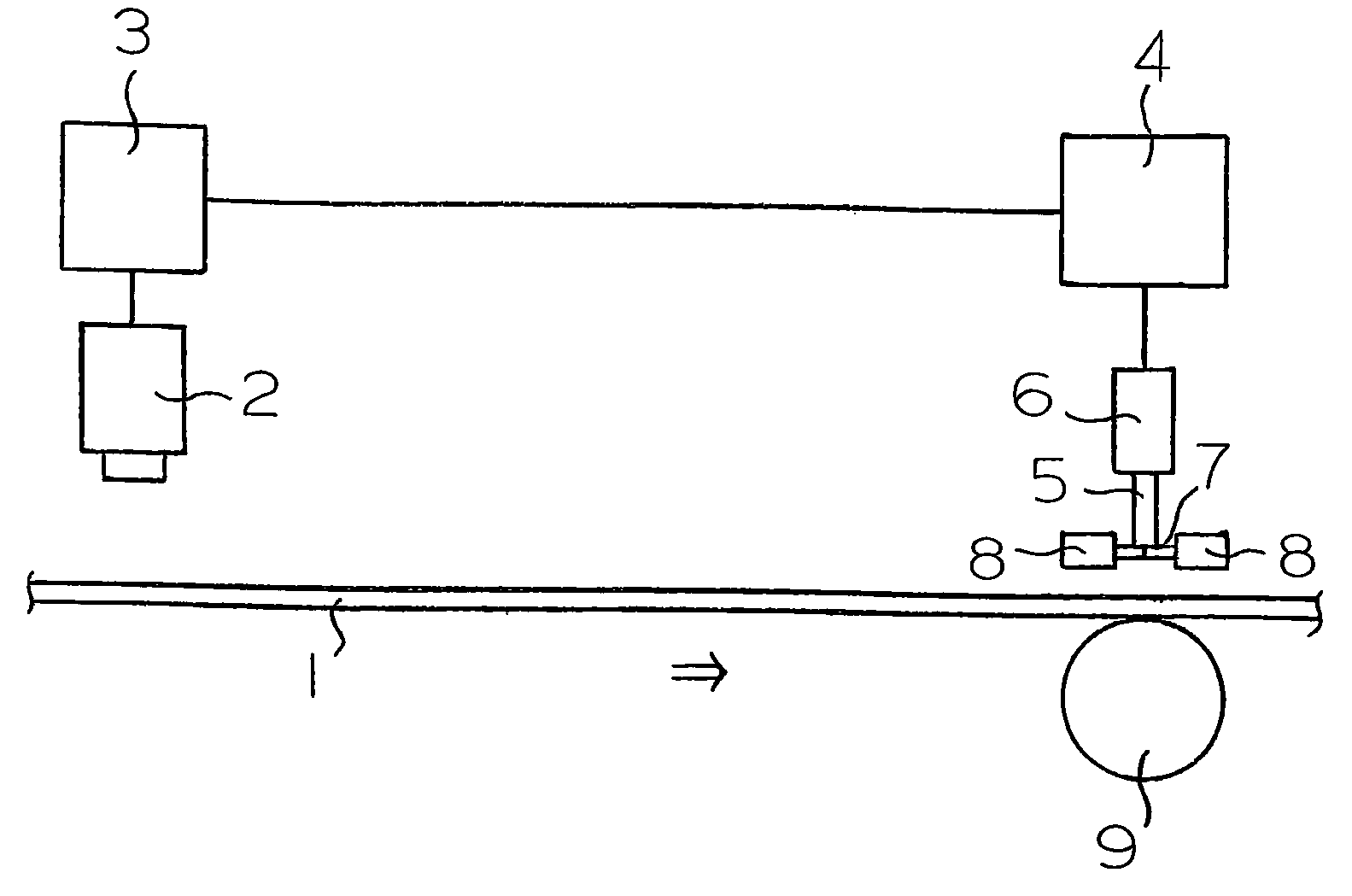
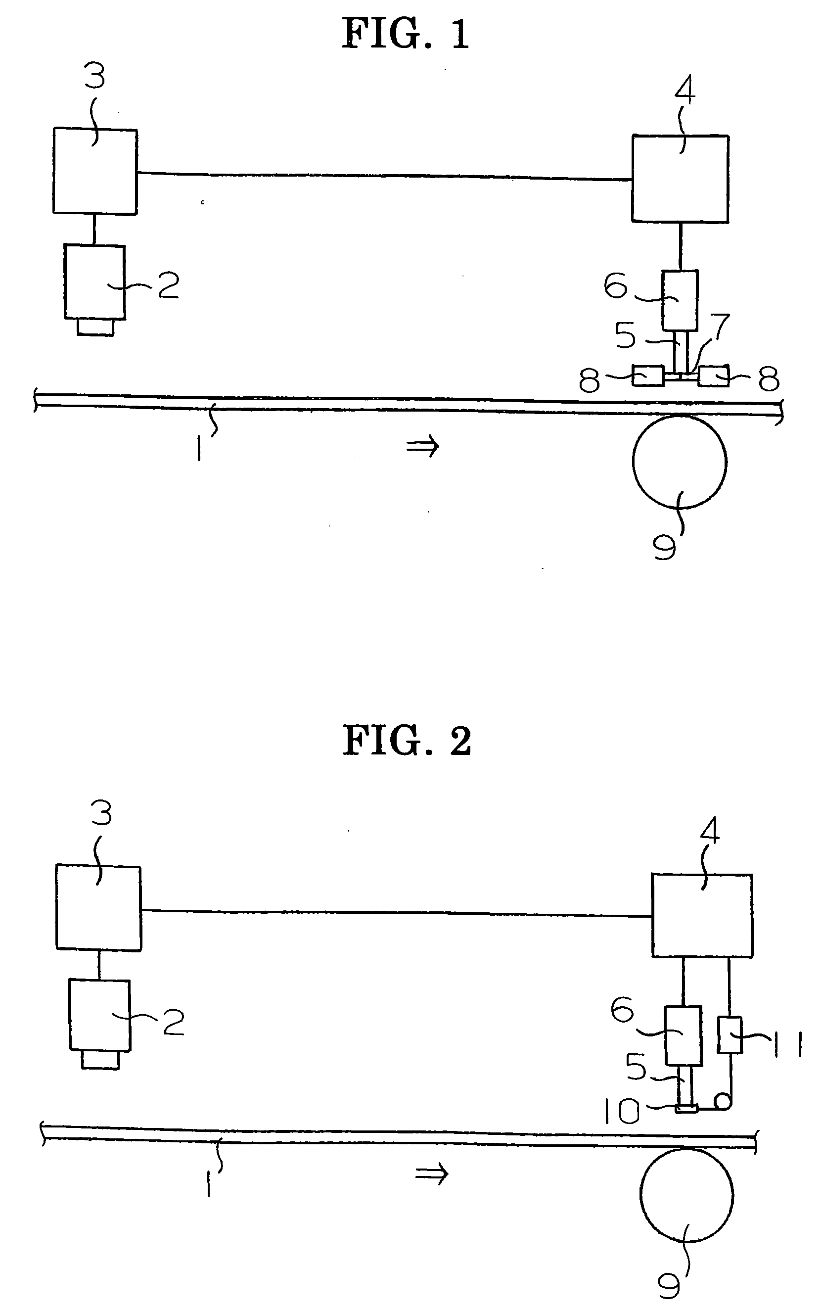
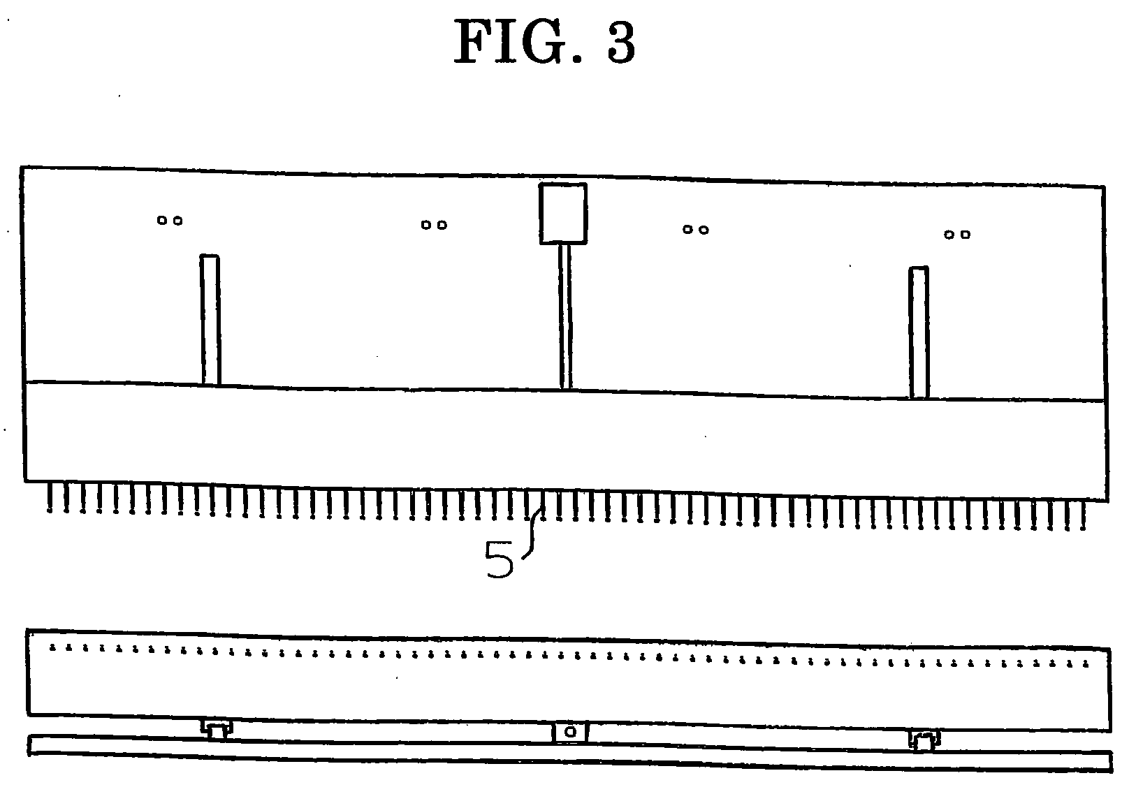
[0238] A biaxially stretched polyethylene terephthalate film having a width of 1,600 mm and a thickness of 50 μm was inspected. Above the polyethylene terephthalate film, 8 CCD cameras were disposed at a distance of 200 mm between each other. Below the polyethylene terephthalate film, light sources were disposed at positions corresponding to the positions of the CCD cameras. Above the polyethylene terephthalate film, a marking head having 64 pairs of a container tube for an oil-based marking pen worked by a solenoid and a shutter of the container tube worked by an air cylinder which were arranged along the line having the length of the width of 1,600 mm at a distance of 25 mm between each other was disposed at a position downstream of the CCD cameras and the light sources by 2.0 m. Below the polyethylene terephthalate film, a supporting roll was disposed at a position facing the marking head.

[0239] As the solvent for the oil-based marking pen, a mixed solvent containing 70% by weig...

example 2

[0241] A biaxially stretched polyethylene terephthalate film having a width of 1,400 mm and a thickness of 100 μm was inspected. Above the polyethylene terephthalate film, 8 CCD cameras were disposed at a distance of 200 mm between each other. Below the polyethylene terephthalate film, light sources were disposed at positions corresponding to the positions of the CCD cameras. Above the polyethylene terephthalate film, a marking head having 70 pairs of a container tube for an oil-based marking pen worked by a solenoid and a shutter of the container tube worked by an air cylinder which were arranged along the line having the length of the width of 1,400 mm at a distance of 20 mm between each other was disposed at a position downstream of the CCD cameras and the light sources by 2.0 m. Below the polyethylene terephthalate film, a supporting roll was disposed at a position facing the marking head.

[0242] As the solvent for the oil-based marking pen, ethanol was used. The tip of the pen ...

example b1

[0245] A polycarbonate material film for a carrier tape for mounting electronic parts having a width of 1,200 mm and a thickness of 0.2 mm was slit to form 60 product films having a width of 20 mm. Above the film, 6 CCD cameras were disposed at a distance of 200 mm between each other. Below the film, light sources were disposed at positions corresponding to the positions of the CCD cameras. Above the film, a marking head having 60 pairs of a container tube for an oil-based marking pen worked by a solenoid and a shutter of the container tube worked by an air cylinder which were arranged along the line having the length of the width of 1,200 mm at a distance of 20 mm between each other was disposed at a position downstream of the CCD cameras and the light sources by 2.0 m. Below the polyethylene terephthalate film, a supporting roll was disposed at a position upstream of the marking apparatus by 5 mm. An inspection apparatus for detecting a defect by processing images taken by the CCD...


PUM


Abstract

An apparatus for marking a defect detects a defect in a long sheet product transferred in a longitudinal direction by an inspection apparatus and places a mark at the defect at a position downstream of the inspection apparatus. An oil-based marking pen is contained in a container tube having a shutter for closing the tip of the pen. The shutter is opened based on a signal sent from the inspection apparatus, a mark is placed at the defect in the long sheet product by the tip of the pen pushed out of the container tube, the pen is pulled back into the container tube after the marking is completed, and the shutter is closed. The mark can be placed at the portion of the detected defect by an oil-based marking pen without causing a decrease in the marking property due to drying of the tip of the pen.

Description

BACKGROUND OF THE INVENTION [0001] 1. Field of the Invention [0002] The present invention relates to an apparatus for marking a defect. More particularly, the present invention relates to an apparatus for marking a defect which detects a defect in a product having a long sheet form and transferred in the longitudinal direction by an inspection apparatus, and places a mark at the portion of the detected defect by an oil-based marking pen without causing a decrease in the marking property due to drying of the tip of the pen. [0003] The present invention also relates to embodiments in which the apparatus for marking a defect by an oil-based marking pen described above is applied to specific apparatuses for marking a defect developed by the present inventors. [0004] Thus, the present invention relates also to an apparatus for slitting a film, and more particularly to an apparatus for slitting a film which detects a defect present in a film when a material film is slit and wound and plac...

Claims


Application Information

Patent Timeline
IPC IPC(8): G01N21/84
CPCG01N21/89G01N2021/888B25B9/02
Inventor SHIBATA, KENRO
Owner NAGASE & COMPANY
Why Eureka
Try Eureka