Fiber optic sensor and sensing system for hydrocarbon flow

a technology of hydrostatic pressure and fiber optic cables, which is applied in the direction of instruments, surveyors, and well accessories, can solve the problems of internal pipe erosion and corrosion, serious problem of liquid hydrocarbon transport, wax and scale buildup in the pipe walls, etc., and achieve the effect of enhancing the responsiveness of fiber optic cables and magnifying the mechanical strain associated

a technology of hydrostatic pressure and fiber optic cables, which is applied in the direction of instruments, surveyors, and well accessories, can solve the problems of internal pipe erosion and corrosion, serious problem of liquid hydrocarbon transport, wax and scale buildup in the pipe walls, etc., and achieve the effect of enhancing the responsiveness of fiber optic cables and magnifying the mechanical strain associated

US20060165344A1Inactive Publication Date: 2006-07-27GE OIL & GAS UK LTD

Image

  • Fiber optic sensor and sensing system for hydrocarbon flow
  • Fiber optic sensor and sensing system for hydrocarbon flow
  • Fiber optic sensor and sensing system for hydrocarbon flow

Examples


Embodiment Construction

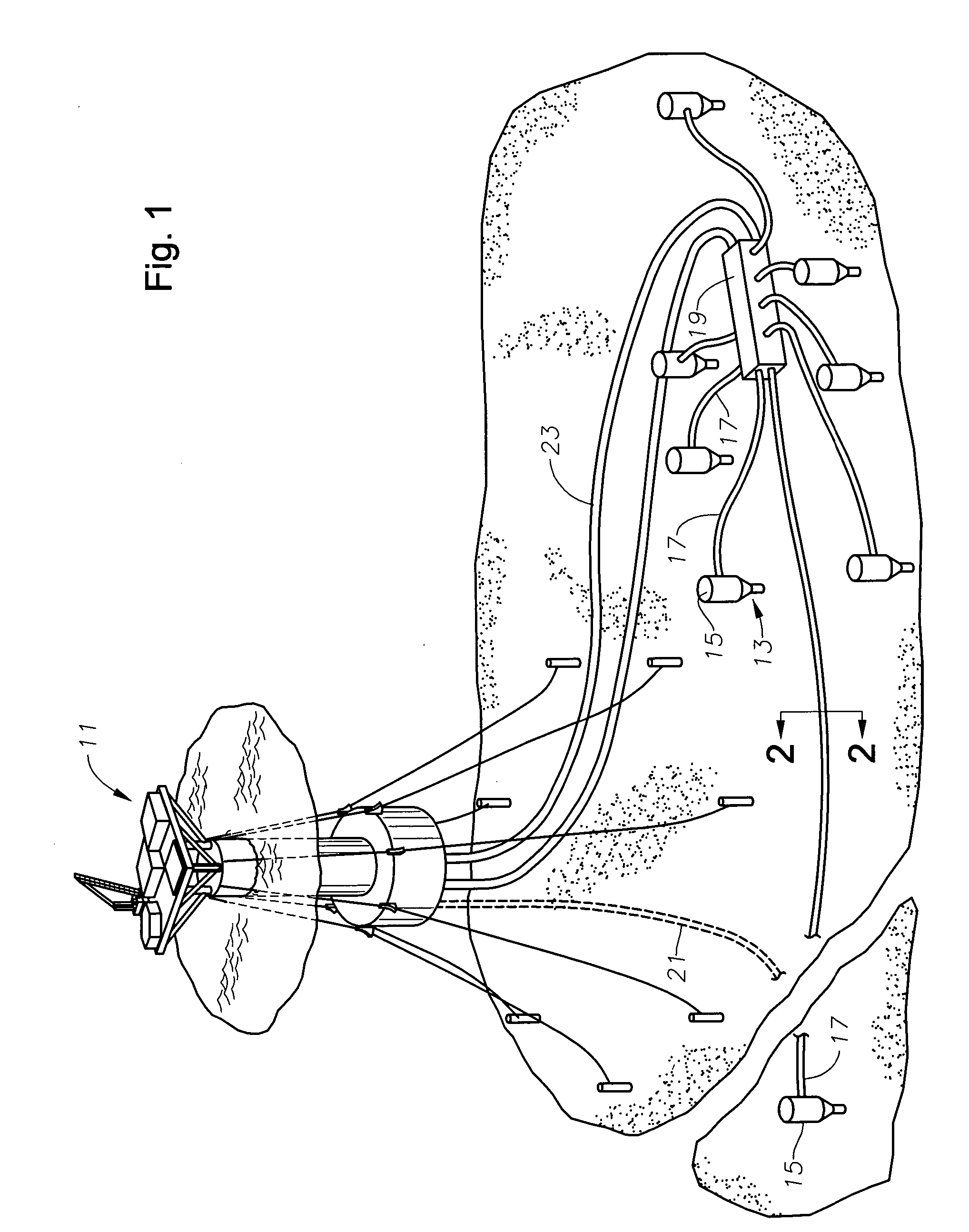
[0025] Referring to FIG. 1, a vessel 11 collects well fluids from subsea wells 13 situated in a cluster on a sea floor 12. Preferably, each subsea well 13 includes a subsea wellhead 15 protruding above the sea floor 12. A production line 17 extends from each wellhead 15 to a collection manifold 19 situated on the subsea floor 12. A riser 23 extends from the collection manifold 19 to the vessel 11 for transferring well fluids from the subsea floor 12 to the vessel 11. As will be readily appreciated by those skilled in the art, the riser 23 can preferably include a plurality of individual risers 23 or a bundle of individual tubular structures for supplying segregated streams of well fluid from the collection manifold 19 to the vessel 11. In some situations, it is desirous to connect production line 17 to vessel 11 via a riser 21 rather than to collection manifold 19 and through common riser 23. While vessel 11 is shown as a floating platform in FIG. 1, vessel 11 is merely representati...


PUM


Abstract

An assembly senses fluid pressure variations within a passageway along a length of a flowline. A fiber optic cable is disposed axially within the passageway of the flowline. The fiber optic cable experiences a mechanical strain responsive to variations in the fluid pressure of the fluid communicating through the passageway of the flowline along the length of the flowline. The assembly also includes an enhancing layer surrounding the fiber optic cable. The enhancing layer is more responsive to the fluid pressure of the fluid communicating through the passageway of the cable than the fiber optic cable, which enhances the responsiveness of the fiber optic cable to the pressure by magnifying the mechanical strain associated with the fiber optic cable within a particular region of varying fluid pressure. Strain associated with the cable is communicated through back-reflected light.

Description

BACKGROUND OF THE INVENTION [0001] 1. Field of the Invention [0002] The present invention relates to an apparatus and method for sensing hydrostatic pressure, in a distributed fashion, in hydrocarbon pipelines and wells. The invention is particularly concerned with the detection and localization of flow restrictions and blockages in hydrocarbon flowlines for flow assurance purposes. [0003] 2. Background of the Invention [0004] As part of the overall process of oil extraction and processing, it becomes necessary to transport the fluids containing liquid hydrocarbons from their reservoirs to remote plants for chemical processing. This transport process is usually conducted and pipelines that can be anywhere from several hundred meters to various kilometers in length. Ensuring the safe, reliable and continuous transport of hydrocarbons through the pipelines is of vital importance to oil companies and hydrocarbon refineries. It is also equally important to properly measure the pressure,...

Claims


Application Information

Patent Timeline
27 Jul 2006
Publication
US20060165344A1
IPC
G02B6/26
CPC
E21B47/06; E21B47/09; G01D5/35364; G01L11/025; G02B6/4464; E21B47/123; E21B47/135; G02B6/52
Inventors
MENDEZ, ALEXIS; DIATZIKIS, EVANGELOS V.