Fluid dynamic bearing device, spindle motor and disk drive

a dynamic bearing and spindle motor technology, applied in sliding contact bearings, instruments, physics instruments, etc., can solve the problems of lubricating oil leakage out of the voids and scattered, increased size of the void, and increased lubricating fluid leakage, so as to avoid the leakage of lubricating fluid, reduce the size, and facilitate the effect of us

Inactive Publication Date: 2006-08-03
NIDEC CORP
View PDF12 Cites 3 Cited by
  • Summary
  • Abstract
  • Description
  • Claims
  • Application Information

AI Technical Summary

Benefits of technology

[0015] The advantage of the invention is conspicuous especially in the application to a small-sized fluid dynamic bearing device or a spindle motor having thin component members.
[0016] According to this invention, the desired distribution of the inclusions is successfully realized with a greater ease by appropriately limiting the components of the free-cutting stainless steel. Especially, by containing Ti together with Mn and Cr in sulfide inclusions, the inclusions are greatly reduced in size and the leakage of the lubricating fluid is avoided.
[0017] In the case where the Ti content is further increased to form inclusions having a Ti sulfide or a Ti nitride as a main component, on the other hand, the cutting performance is adversely affected in spite of a further reduced size. According to the invention, the machinability is maintained by appropriating controlling the Ti content. In the fluid dynamic bearing device according to the invention, therefore, the lubricating fluid is hard to leak and the machining operation for device fabrication can be carried out easily with a high productivity.
[0018] According to this invention, the free-cutting stainless steel composition can be produced by the continuous casting process, and therefore the production cost is further reduced.
[0019] Generally, the continuous casting process is executed in such a manner that melted steel is injected from one side of a water-cooled mold and cast iron is drawn from the other side. Impurities such as S, therefore, are liable to be deposited in the neighborhood of the central part of the cast iron and large inclusions of sulfide are liable to be formed. In the case where the direction in which the cast iron is drawn coincides with the direction of rolling, the inclusions extended long in the direction of rolling are formed more easily. In view of this disadvantage, a small ingot about 50 kg in weight is sometimes cast without using the continuous casting process to prevent large inclusions from being formed. The Ti—Cr—S inclusions are comparatively less affected by these casting conditions, and even when fabricated by the continuous casting process, hardly produce large inclusions. In the case where the Mn—Cr—S inclusions more liable to be formed as large inclusions are the sole inclusions, the continuous casting process is not desirable especially for the small-sized fluid dynamic bearing device. The coexistence of the Mn—Cr—S inclusions with the Ti—Cr—S inclusions, however, suppresses the formation of large inclusions and makes it possible to use the continuous casting process.
[0020] Other features, elements, steps, advantages and characteristics of the present invention will become more apparent from the following detailed description of preferred embodiments thereof with reference to the attached drawings.

Problems solved by technology

These protrusions become particles and intrude into the sliding part of the bearing members, thereby often posing a serious lubrication problem.
It has been found that in the case where the voids are formed through the thin parts of a member, the lubricating oil leaks out of the voids and scattered during the relative rotation of the fluid dynamic bearing device.
Also, in the case where the voids come to communicate with each other, the size thereof is increased to such an extent that the lubricating oil further leaks out and scatters.

Method used


Image

  • Fluid dynamic bearing device, spindle motor and disk drive
  • Fluid dynamic bearing device, spindle motor and disk drive
  • Fluid dynamic bearing device, spindle motor and disk drive

Examples


Embodiment Construction

[0041] A fluid dynamic bearing device according to each embodiment of the invention is explained below reference to the drawings, together with a spindle motor using the device. This invention is not limited to the embodiments described below.

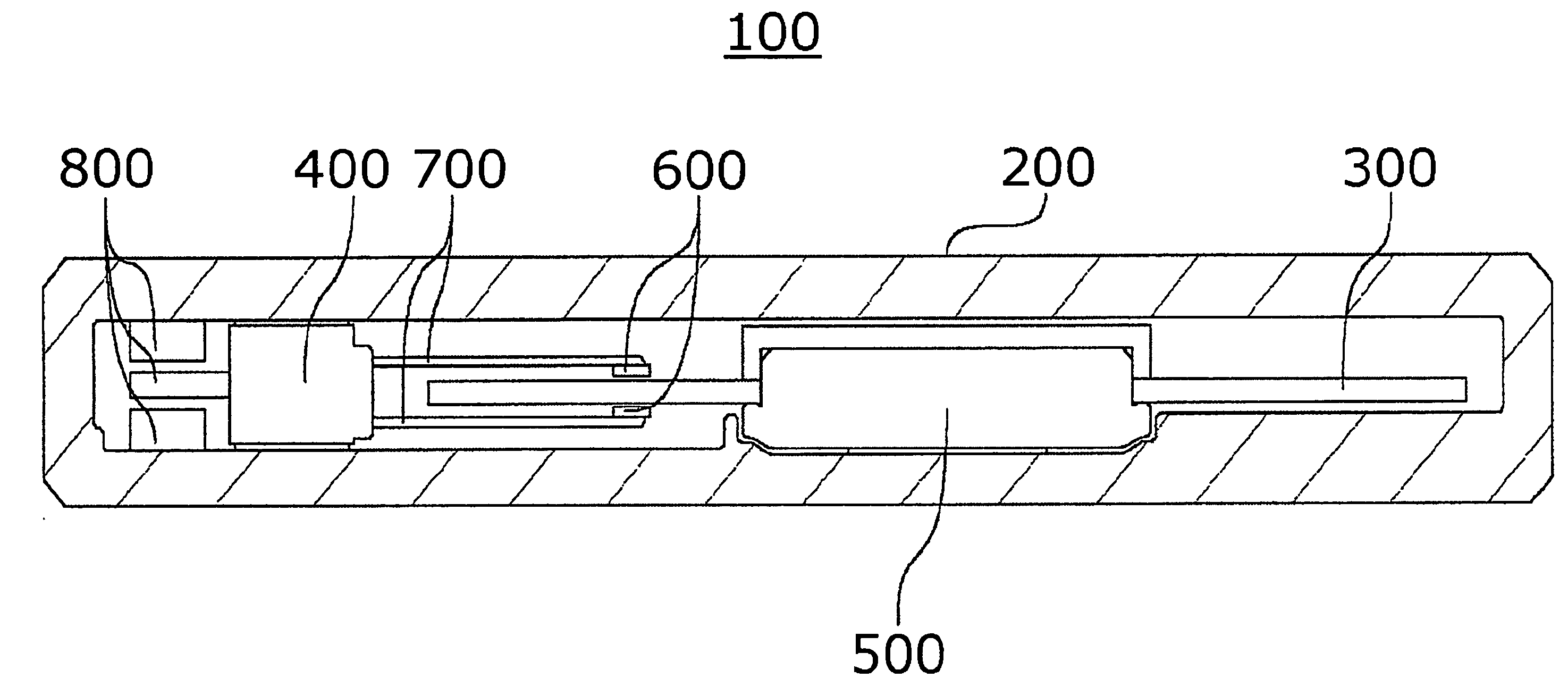
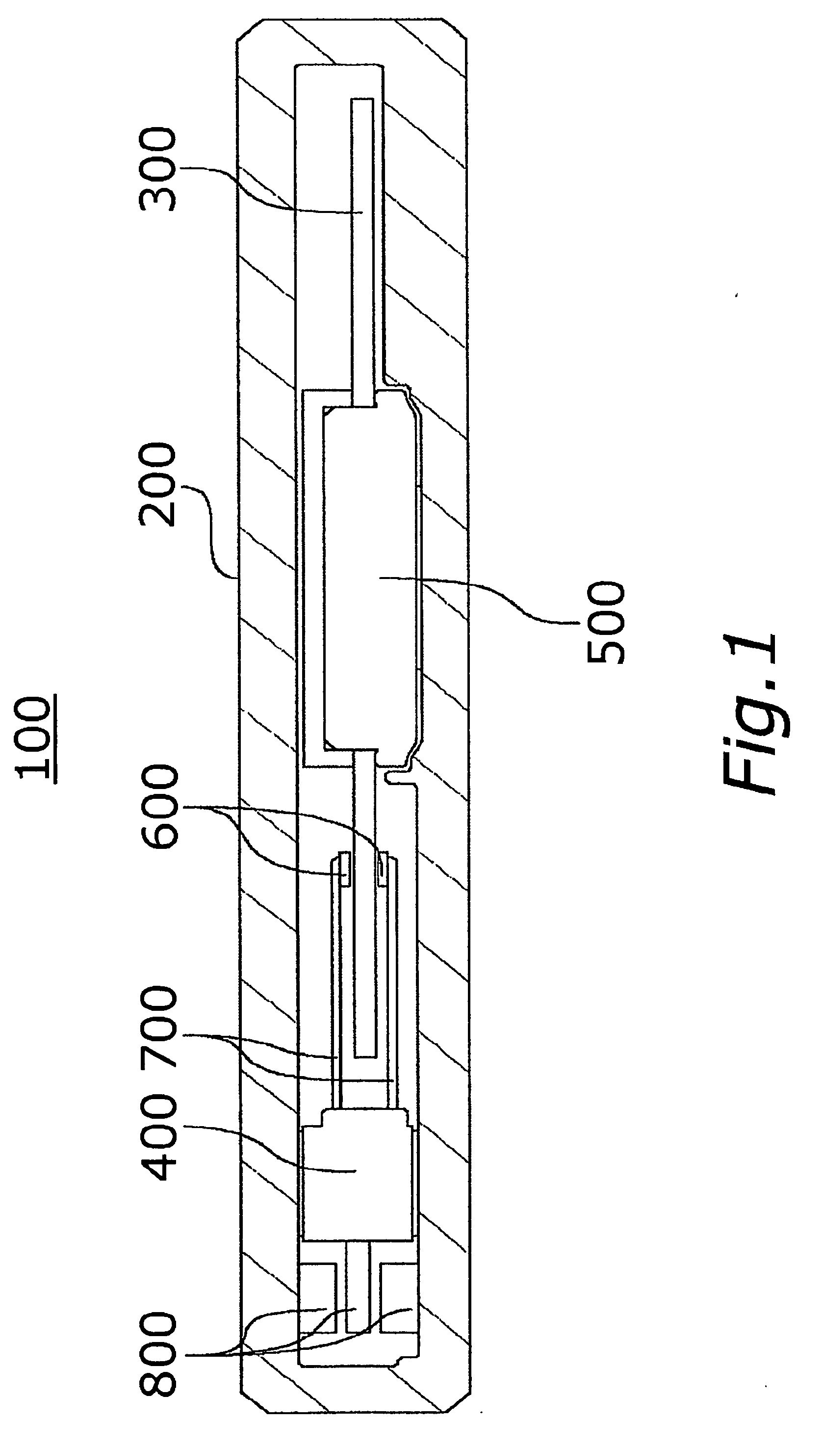
[0042]FIG. 1 is a longitudinal sectional view schematically showing a disk drive apparatus 100 according to an embodiment of the invention. This disk drive apparatus 100 is a small-sized thin hard disk drive, for example, for rotating a small recording disk such as a small hard disk having the outer diameter of not more than 2.5 inches (in particular, not more than 1 inch).

[0043] The component parts of the disk drive apparatus 100 are accommodated in a housing 200 and mainly include a recording disk 300, a magnetic head moving mechanism 400 and a spindle motor 500.

[0044] The recording disk 300 is a discal member having a magnetic recording layer of a magnetic material capable of recording information by magnetism. A small recording disk 300 ...


PUM

PropertyMeasurementUnit
diameteraaaaaaaaaa
diameteraaaaaaaaaa
diameteraaaaaaaaaa

Abstract

A fluid dynamic bearing device, a spindle motor and a disk drive apparatus are disclosed. A highly accurate fluid dynamic bearing member of the fluid dynamic bearing device can be formed of a free-cutting stainless steel composition easy to cut or otherwise machine, while at the same time preventing the leakage and scattering of a lubricating fluid. At least one of the two bearing surfaces formed with a dynamic pressure generating groove of the fluid dynamic bearing mechanism is formed of the free-cutting stainless steel composition. The average short diameter of the inclusion particles on the ground surface of the free-cutting stainless steel composition is between 1 μm and 10 μm inclusive, and the average long diameter thereof is between 1 μm and 30 μm inclusive.

Description

BACKGROUND OF THE INVENTION [0001] 1. Field of the Invention [0002] This invention relates to a fluid dynamic bearing device for rotatably supporting a rotary member on a fixed member using a fluid dynamic bearing, a spindle motor and a disk drive apparatus. [0003] 2. Description of the Related Art [0004] In recent years, efforts have been made variously to develop a fluid dynamic bearing device for rotatably supporting various high-speed rotary members including a polygon mirror, a magnetic disk and an optical disk. The fluid dynamic bearing device includes a dynamic bearing surface on the rotary member side and a dynamic bearing surface on the fixed member side arranged radially or axially in opposed relation to each other with a predetermined gap therebetween, and a dynamic bearing portion is formed in the gap. A dynamic pressure generating groove is formed on at least one of the opposed dynamic bearing surfaces. A lubricating fluid such as air or oil is injected into the dynamic...

Claims


Application Information

Patent Timeline
Patent Type & Authority Applications(United States)
IPC IPC(8): F16C32/06
CPCC21D6/004C22C38/02C22C38/04C22C38/18C22C38/28C22C38/60F16C17/107F16C33/107F16C33/12G11B19/2036F16C33/121F16C2370/12
Inventor KASHIWA, NAOKONAKANISHI, MAKOTOOKADA, TAKAYUKI
Owner NIDEC CORP
Why Eureka
Try Eureka